Two Multi-Directional Die Forging Methods for Ball Valve Bodies
Two Multi-Directional Die Forging Methods for Ball Valve Bodies
Jan 11, 2025
Ball valve bodies are critical components in valves, traditionally manufactured through casting. However, casting is prone to defects such as porosity, shrinkage, and dendritic formation, which can prevent valves from meeting performance requirements in harsh operating conditions. To enhance the mechanical properties of ball valve bodies, researchers and manufacturers have turned to forging techniques, particularly free forging and die forging. These methods, however, generate substantial material waste and incur high machining costs. Recent advancements in heavy equipment technology have made the multi-directional die forging process widely adopted. This process is characterized by high material utilization, continuous internal fiber alignment, and superior mechanical properties in forged components. This paper introduces two distinct ball valve body forming processes using the multi-directional die forging method.
The ball valve body (Figure 1) is a component with flanges at both ends, a smaller central diameter, and larger diameters at the flanges. Symmetrically positioned bosses of varying sizes are present on the ball flange side. Made of carbon steel, the valve body weighs 128 kg, with a designed forging weight of 207 kg and a material utilization rate of approximately 62%.
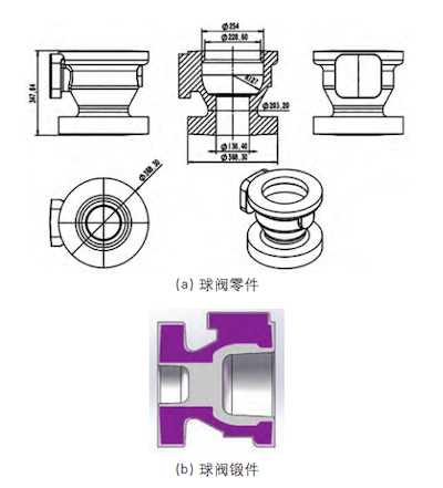
(a) Ball valve components (b) Forged ball valve bodies
Figure 1: Ball valve body components and forged parts
Producing this forged valve in a single operation using conventional forging methods poses significant challenges. Multi-directional die forging technology, in combination with heavy equipment, applies pressure to the blank within a separable die cavity from multiple directions, enabling the production of complex shapes. The primary methods of multi-directional die forging include horizontal splitting, vertical splitting, and combined splitting. This paper introduces two multi-directional die forging schemes—horizontal splitting and vertical splitting—for manufacturing this ball valve body. Both methods meet the required forging quality standards, differing primarily in their equipment load requirements and mold splitting structures.
The valve body features large flanges at both ends, a smaller central diameter, and significant size variation along the flange axis. The multi-directional die forging process begins with blanking the material, as shown in Figure 2.
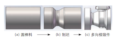
(a) Round bar stock (b) Blanking (c) Multi-directional die-forged parts
Figure 2: Horizontal split die forming process
The horizontal split die method uses multi-directional die forging. In this process, the heated preform is placed in the multi-directional die. Forging occurs within the die cavity, with the die surface aligned to the forging's maximum horizontal projection. Figure 3 shows the structure of the horizontal split die used in multi-directional forging.
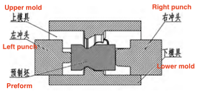
Figure 3: Horizontal split die structure
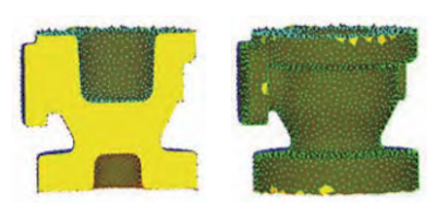
Figure 4: Metal flow and cavity filling during forging
Round bar stock is selected for free forging. After heating the billet, an infrared thermometer is used to measure its surface temperature. If the billet’s temperature falls below 850°C, it is returned to the furnace for reheating and holding before proceeding with multi-directional die forging. If the temperature exceeds 1050°C, multi-directional die forging can proceed immediately.
Horizontal punches on both sides compress the preform within the closed mold cavity, causing the metal to flow and fill the cavity. The final forming takes place at the larger convex region of the valve body. The forging produced by multi-directional die forging demonstrates excellent surface quality, with a fully formed metal structure and no defects, such as folding in the inner hole or surface irregularities.
Numerical simulations of the forming force help determine the load required for plastic forming, providing valuable insights for production tests. This study used a comprehensive three-dimensional mold model for numerical simulation analysis (Figure 5). The maximum horizontal forming load was 66.4 MN, while the maximum clamping load reached 65.2 MN.
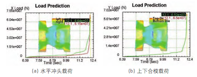
(a) Horizontal punch load (b) Upper and lower clamping load
Figure 5: Die force analysis during forging
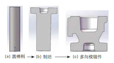
(a) Round bar material (b) Blanking (c) Multi-directional die-forged components
Figure 6: Horizontal split die forming
The valve body features large flanges at both ends, with significant size variations between the central section and the flanges. The blank must be selected according to the dimensions of the valve's smallest section. Upsetting the flange on one side can result in folding defects and instability in the inner hole of the flange. In the vertical split die forming scheme, the process begins with upsetting and consolidating the bar material, followed by extrusion to shape the concave hole.
The initial step involves upsetting and consolidating the bar material, followed by extrusion to form the desired shape. The next step involves upsetting, consolidation, and deep-hole forming using the vertical split die with multi-directional forging equipment. Figure 7 illustrates the deep-hole forming process in the second step.
Due to the large flanges on both sides of the ball valve body, additional metal must be added, increasing the complexity of the filling process. The original bar is first forged into a blank to form a flange on one side, then placed in the cavity of the multi-directional die for forging. Throughout the process, the temperature of the preform must be closely monitored. If the temperature drops below 850°C, the preform is returned to the furnace for reheating and holding. If the preform temperature exceeds 1050°C, forging can proceed directly without reheating.
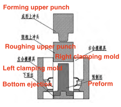
Figure 7: Deep-hole forming process in the vertical split die scheme
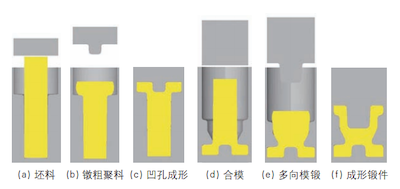
(a) Blank (b) Upsetting the aggregate material (c) Forming the concave hole (d) Clamping (e) Multi-directional die forging (f) Final forging
Figure 8: Process flow for forming the ball valve body

(b) Final forging upper punch load (b) Preform upper punch load (c) Left and right clamping load
Figure 9: Die force analysis during the forging process
Figure 8 depicts the forming process flow for the ball valve body in the vertical split die scheme, requiring two sets of concave dies. The process begins with upsetting and consolidating the bar material, followed by forming the concave hole at the base of the flange, as shown in Figures 8(b) and 8(c). The preform is positioned within the multi-directional forging die cavity, aligning the concave hole at the flange base with the convex portion of the lower ejection die. The left and right dies are then clamped together. The preform is upset and consolidated by the upper punch, and subsequently, the blank is extruded and shaped using the forming punch, as depicted in Figures 8(d), 8(e), and 8(f). The forming process employs a total of four upper punches. As the upper punches play a critical role, prompt replacement during production is essential to maintain the quality of the forged part. A flexible and automated mechanism for upper punch replacement is required to ensure continuous production.
The initial pre-forging load is 43.7 MN, as illustrated in Figure 9(a). The extrusion load for the punch during multi-directional forging is 47 MN, which forms the large end flange and the convex joint on the valve body, as shown in Figure 9(b). The maximum left and right clamping load for the vertical split die is 54.2 MN, ensuring the stability of the valve body during forming and optimal forging quality, as shown in Figure 9(c).
- Die Splitting Structure: In the horizontal splitting scheme, the splitting surface is oriented horizontally, while in the vertical splitting scheme, it is oriented vertically.
- Different Forming Steps: To achieve consistent forging dimensions in both splitting schemes, the preform in the vertical splitting scheme requires multiple upsetting and consolidation steps. Consequently, the vertical splitting scheme involves more steps than the horizontal scheme does.
- Different Forming Loads: Simulation results show that the mold load in the horizontal splitting scheme is higher than that in the vertical scheme. In the vertical scheme, the blank undergoes roughening and consolidation before flange formation on both sides, which reduces resistance during the later stages of metal flow.
- Forming Challenges: The side boss area of the ball valve body presents the greatest challenge during forging, as it is difficult to achieve full metal filling. This area also experiences high resistance to metal flow.
Research on the ball valve body forging process indicates that achieving the same forging size with the vertical splitting scheme requires multiple material consolidation steps before the punch can form a deep hole. Directly upsetting and compressing the original blank may cause folding inside the hole, resulting in scrap. Trial production results align with the simulation outcomes. Thus, the ball valve forging described in this study should utilize the horizontal splitting scheme. This scheme conserves raw materials and simplifies the forming process, while imposing greater demands on the equipment's load capacity.
Next: Optimization of the Forging Process for F92 Large Valve Body
Previous: Ultra-High-Pressure Forged Self-Sealing Pre-Start Control Valve