Optimization of the Forging Process for F92 Large Valve Body
Optimization of the Forging Process for F92 Large Valve Body
Feb 26, 2025
ASTM A182 F92 is susceptible to surface cracking under improper forging due to its high alloy content. Additionally, its high chromium (Cr) and tungsten (W) content significantly reduces the effectiveness of conventional flame-based defect detection methods, which in turn reduces production efficiency. Severe surface cracks may render the product non-compliant with quality standards. Therefore, optimizing the forging process for F92 large valve is essential.
ASTM A182 F92 complies with ASTM A182/A182M-2018, the standard for forged or rolled alloy steel and stainless steel components used in high-temperature applications. It is a martensitic heat-resistant steel. The increased tungsten (W) and molybdenum (Mo) content enhances its high-temperature corrosion resistance, low-cycle thermal fatigue resistance, and creep rupture strength. The chemical composition of F92 is detailed in Table 1. The high alloy content of F92 increases resistance to hot deformation, narrows the forging temperature range, and raises the risk of surface cracking. Grain size control during forging is essential to maintaining material quality. Therefore, strict forging process control is essential for producing high-quality F92 large valve body forgings.
After upsetting the steel ingot, the WHF (Weight Hammer Forging) center compaction method, wide anvil feed, and a minimum 20% reduction in forging are applied to shape the blank. This ensures effective plastic deformation of the forging blank core under three-dimensional compressive stress, refining the coarse as-cast structure and eliminating internal cavity defects. Using the forging of a 15-ton steel ingot as an example, the forging process design is outlined as follows:
- Step 1: Perform chamfering, secure the workpiece, and ensure a dry surface.
- Step 2: Upset the ingot to a height of 865 mm and a diameter of 1500 mm. Use a 900 mm wide anvil for stretching, maintaining an anvil width ratio of 0.6 to 0.8. Refer to Table 2 for pressure control parameters, and rotate the ingot 90° sequentially.
During forging, the F92 steel billet may develop surface cracks under high forging pressure, which can occur during both the upsetting process (Figure 1a) and the stretching process (Figure 1b). In severe cases, these cracks can disrupt the forging process, potentially rendering the billet unusable.
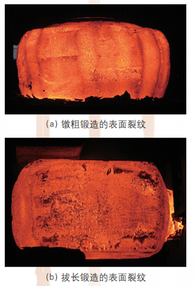
(a) Surface cracking during upsetting (b) Surface cracking during stretching
Figure 1: Surface Cracking
Therefore, forging process optimization aims to minimize surface cracking in large F92 steel billets while enhancing core deformation, refining the coarse as-cast structure, and eliminating internal cavity defects to achieve a uniform microstructure.
|
Composition |
Standard |
|
C |
0.07 - 0.13 |
|
Si |
≤ 0.50 |
|
Mn |
0.30 - 0.50 |
|
P |
≤ 0.018 |
|
S |
≤ 0.010 |
|
Cr |
8.50 - 9.50 |
|
Mo |
0.30 - 0.60 |
|
W |
0.15 - 2.00 |
|
V |
0.15-0.25 |
|
Nb |
0.04 - 0.09 |
|
N |
0.03 - 0.07 |
|
B |
0.001 - 0.006 |
|
Ni |
≤ 0.40 |
|
Al |
≤ 0.020 |
|
Cu |
0.20 |
|
Pass Number |
Before Pressing (Reference) / mm |
After Pressing (Control) / mm |
Anvil Feed / mm |
|
2 |
1500 |
1275 |
900 |
|
3 |
1564 |
1175 |
900 |
|
4 |
1371 |
1100 |
900 |
|
5 |
1311 |
1050 |
800 |
|
6 |
1233 |
985 |
800 |
|
7 |
1180 |
950 |
750 |
Strain Rate: Strain rate refers to the rate of deformation per unit time and is measured in s⁻¹.

According to Gleeble thermal deformation tests at 1200°C, the stress-strain curve for ASTM A182 F92 under different strain rates is shown in Figure 2. As the strain rate increases, the material's flow stress also increases. Therefore, when significant deformation is required during forging, the strain rate must be strictly controlled. To optimize forging conditions, maintain the strain rate at or below 0.5 s⁻¹.
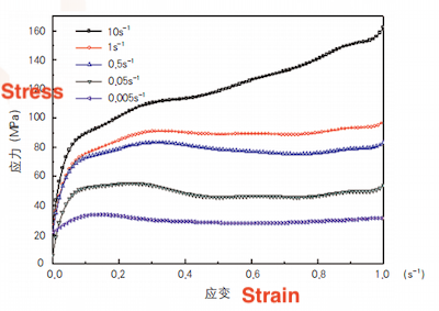
Figure 2: High-Temperature Stress-Strain Curve of F92 at 1200°C Under Different Strain Rates
As illustrated in Figure 3, the high-temperature stress-strain curve of F92 at a strain rate of 0.005 s⁻¹ under different temperature is shown. As the temperature increases, the deformation resistance of F92 decreases, while the softening effects of recovery and recrystallization become more pronounced. When the temperature exceeds 1000°C, the material's deformation resistance reduces to below 110 MPa. To achieve significant deformation during forging, maintain the forging temperature above 1000°C whenever feasible. Based on this analysis, the following process improvements are proposed:
- Reduce the degree of upsetting. After upsetting, briefly reheat the forging billet in the furnace to increase its surface temperature.
- Control the deformation rate by increasing the anvil feed, reducing the forging reduction to 15–20%, and increasing the number of forging passes. This ensures that the overall forging ratio remains unchanged while lowering the deformation rate and ensuring effective core forging.
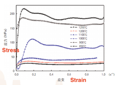
Figure 3 High-temperature stress-strain curves of F92 steel at different temperatures at a strain rate of 0.005 s⁻¹
Using a 15-ton steel ingot as an example, and considering the reduced upsetting and reduction during the lengthening process, the optimized forging process design is as follows:
Step 1: Chamfer the ingot, clamp it, and remove surface moisture.
Step 2: Upset to H = 990 mm and 1400 mm. Use upper and lower plates to shape the ingot into a square according to the specifications in Table 3 for the first and second passes, followed by brief reheating in the furnace.
Step 3: Use a 1200 mm wide anvil for drawing, maintaining an anvil width ratio of 0.8–1.1. Apply the pressure settings shown in Table 3 (passes 2–8), rotating the ingot 90° sequentially.
Deform analysis software was used to simulate and compare the core forging penetration of the optimized process with that of the process before optimization. The billet dimensions were set at 1230 mm × 1150 mm (square). The selected parameters were as follows:
- Before optimization, the parameters were as follows: anvil width of 900 mm, a 20% reduction, a strain rate of 0.004 s⁻¹, and a deformation temperature of 1100°C.
- After optimization, the anvil width was increased to 1200 mm, while the reduction was adjusted to 15%, with the strain rate and deformation temperature remaining at 0.004 s⁻¹ and 1100°C, respectively.
For billets of the same size, the equivalent stress and strain rate distributions are shown in Figures 4 and 5.
Simulation analysis and comparison demonstrate that the stress and strain conditions at the billet core are similar in both processes, confirming that core forging can be effectively achieved.
Through process optimization, a 1200 mm wide anvil was used, and the reduction rate was set to 15%. The results, shown in Figure 6, demonstrate that the surface cracking was effectively addressed. The final product passed flaw detection and met NB/T 47013-2015 Level 1 requirements. The product was successfully delivered.
|
Pass Number |
2 |
3 |
4 |
5 |
6 |
7 |
8 |
|
Before Pressing (Reference) |
1400 |
1485 |
1319 |
1230 |
1230 |
1150 |
1150 |
|
After Pressing (Control) |
1190 |
1120 |
1100 |
1040 |
1030 |
980 |
950 |
|
Anvil Feed Width (mm) |
1200 |
1000 |
1000 |
1000 |
1000 |
800 |
- |
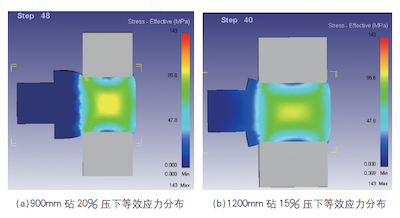
(a) Distribution of equivalent stress with a 900mm anvil and 20% compression
(b) Distribution of equivalent stress with a 1200mm anvil and 15% compression
Figure 4: Comparison of equivalent stress distribution
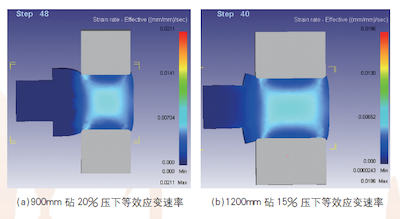
(a) Equivalent strain rate with a 900mm anvil and 20% compression
(b) Equivalent strain rate with a 1200mm anvil and 15% compression
Figure 5 Comparison of equivalent strain rates
- Optimizing the height-to-diameter ratio of the forging billet after upsetting effectively prevents surface cracking caused by excessive deformation.
- After upsetting, the forging billet is reshaped into a square using upper and lower plates, then briefly reheated in the furnace to raise the surface temperature, facilitating subsequent large deformation during the stretching process.
- The use of wide anvils for stretching forging requires high press tonnage, making the selection of an appropriate press tonnage a critical factor in process optimization.
- During wide-anvil stretching, the reduction must be carefully controlled, particularly in the final stage of the downstroke.
- After process optimization, surface cracks are effectively minimized, and the core compaction requirements of the forging billet are successfully met.
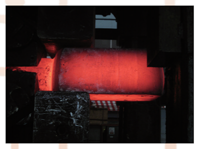
Figure 6 Drawing effect after process optimization
Next: Optimized Manufacturing Process for F304 Steel Valve Body Forgings
Previous: Two Multi-Directional Die Forging Methods for Ball Valve Bodies