The Processing of Guide Grooves of Forged Steel Gate Valves' Wedges
The Processing of Guide Grooves of Forged Steel Gate Valves' Wedges
Apr 20, 2021
Abstract
The production efficiency of the forged steel gate valve's wedge is improved by improving the processing method of guide grooves of the forged steel gate valve's wedges.
A forged steel gate valve is used to connect and stop the flow in the pipeline. A forged steel gate valve is widely used in water, oil, natural gas, food and other industries due to its characteristics of low flow resistance, flexible opening and closing, long service life, compact structure, safety and reliability. The rapid development of China's industry and development of the export market makes the demand for forged steel gate valves increase dramatically, which requires valve manufacturers to continuously improve the processing technology and strive to increase production capacity under the premise of ensuring product quality.
The guide groove of the gate valve's wedge is in the inner cavity of the valve body. Its structure is shown in Figure 1. The four angular grooves and blind holes in the middle cavity form guide grooves of wedges. The structure of the wedge is shown in Figure 2. The angles 1, 2, 3, and 4 are respectively placed at 1, 2, 3, and 4 of guide grooves of valve bodies.
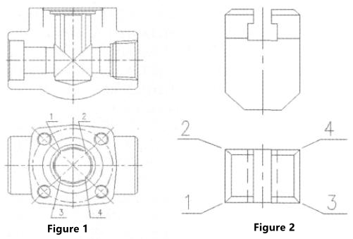
The guide groove on the valve body restricts the movement direction of the wedge so that the wedge can only move up and down along the guide groove to realize the opening and closing of the wedge. If the wedge's guide groove is not processed well, it will not only affect the product quality but also affect production efficiency.
1. The general method of processing the guide groove of the wedge is to first machine the cavity hole and step size of the valve body, and then fix the valve body on the workbench of the slotting machine with a fixture; the valve body is processed by the slotting tool. This processing method has the following shortcomings: First, the processing speed is slow. It takes 5 minutes to process a valve body of DN25. Second, the processing accuracy is difficult to guarantee. Because the processing accuracy of this processing method depends on the technical level of the workers, it is prone to defects such as being crooked, as shown in Figure 3.
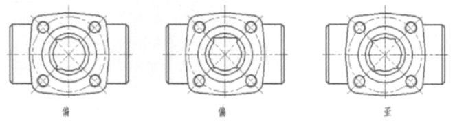
Figure 3
2. The new processing method of guide grooves of wedges: use an ordinary four-column hydraulic press and add positioning devices and fixtures to the machine. As shown in Figure 4, the tooling is mainly composed of four-column hydraulic presses, forming slotting tools, positioning plates of valve bodies, valve bodies (workpieces), clamping columns of valve bodies, guide plates of valve bodies' clamping columns, hydraulic slope plates, hydraulic devices, and travel control units. The cross section of the slotting tool has a quadrilateral shape, which has the same size as the guide groove of valve bodies, and its end face has knife edges on four sides. Therefore, the dimensional accuracy of the wedge's guide groove is controlled by the size of the tool, and there will be no difference in size. The tool is connected with the movable working plate on the main oil cylinder, and the upper and lower movement of the tool can be realized by controlling the main oil cylinder. The valve body positioning plate restricts the relative position of the valve body and the tool. The vertical centerline of the valve body coincides with that of the tool to ensure the position accuracy of the guide groove. 3, 6, 7, and 8 constitute the clamping device of the valve body. The lower end of the clamping top column 6 is an inclined plane, which coincides with the inclined plane of the inclined plate 8. Driven by the auxiliary cylinder of the hydraulic machine, when the inclined plate 8 moves forward, clamping top columns are moved upward to realize the clamping of the valve body. When the inclined plate moves backward, the clamping top column will automatically move downwards under the action of gravity to release the clamping of the valve body. When the tool is adjusted and the valve body is clamped, press the main cylinder button to make the tool go down and remove the iron filings. When the tool is moved to the appropriate position, the travel switch works to make tools move up, and the tool will withdraw. At this time, press the auxiliary cylinder button, and the inclined plate 8 withdraws. The valve body is removed, and then the next valve body is clamped and processed.
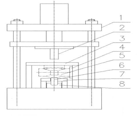
Figure 4
3. The technical and economic effects of the new processing method and general processing method of valve bodies DN25 are compared in the following table:
The production efficiency of the forged steel gate valve's wedge is improved by improving the processing method of guide grooves of the forged steel gate valve's wedges.
A forged steel gate valve is used to connect and stop the flow in the pipeline. A forged steel gate valve is widely used in water, oil, natural gas, food and other industries due to its characteristics of low flow resistance, flexible opening and closing, long service life, compact structure, safety and reliability. The rapid development of China's industry and development of the export market makes the demand for forged steel gate valves increase dramatically, which requires valve manufacturers to continuously improve the processing technology and strive to increase production capacity under the premise of ensuring product quality.
The guide groove of the gate valve's wedge is in the inner cavity of the valve body. Its structure is shown in Figure 1. The four angular grooves and blind holes in the middle cavity form guide grooves of wedges. The structure of the wedge is shown in Figure 2. The angles 1, 2, 3, and 4 are respectively placed at 1, 2, 3, and 4 of guide grooves of valve bodies.
The guide groove on the valve body restricts the movement direction of the wedge so that the wedge can only move up and down along the guide groove to realize the opening and closing of the wedge. If the wedge's guide groove is not processed well, it will not only affect the product quality but also affect production efficiency.
1. The general method of processing the guide groove of the wedge is to first machine the cavity hole and step size of the valve body, and then fix the valve body on the workbench of the slotting machine with a fixture; the valve body is processed by the slotting tool. This processing method has the following shortcomings: First, the processing speed is slow. It takes 5 minutes to process a valve body of DN25. Second, the processing accuracy is difficult to guarantee. Because the processing accuracy of this processing method depends on the technical level of the workers, it is prone to defects such as being crooked, as shown in Figure 3.
Figure 3
2. The new processing method of guide grooves of wedges: use an ordinary four-column hydraulic press and add positioning devices and fixtures to the machine. As shown in Figure 4, the tooling is mainly composed of four-column hydraulic presses, forming slotting tools, positioning plates of valve bodies, valve bodies (workpieces), clamping columns of valve bodies, guide plates of valve bodies' clamping columns, hydraulic slope plates, hydraulic devices, and travel control units. The cross section of the slotting tool has a quadrilateral shape, which has the same size as the guide groove of valve bodies, and its end face has knife edges on four sides. Therefore, the dimensional accuracy of the wedge's guide groove is controlled by the size of the tool, and there will be no difference in size. The tool is connected with the movable working plate on the main oil cylinder, and the upper and lower movement of the tool can be realized by controlling the main oil cylinder. The valve body positioning plate restricts the relative position of the valve body and the tool. The vertical centerline of the valve body coincides with that of the tool to ensure the position accuracy of the guide groove. 3, 6, 7, and 8 constitute the clamping device of the valve body. The lower end of the clamping top column 6 is an inclined plane, which coincides with the inclined plane of the inclined plate 8. Driven by the auxiliary cylinder of the hydraulic machine, when the inclined plate 8 moves forward, clamping top columns are moved upward to realize the clamping of the valve body. When the inclined plate moves backward, the clamping top column will automatically move downwards under the action of gravity to release the clamping of the valve body. When the tool is adjusted and the valve body is clamped, press the main cylinder button to make the tool go down and remove the iron filings. When the tool is moved to the appropriate position, the travel switch works to make tools move up, and the tool will withdraw. At this time, press the auxiliary cylinder button, and the inclined plate 8 withdraws. The valve body is removed, and then the next valve body is clamped and processed.
Figure 4
3. The technical and economic effects of the new processing method and general processing method of valve bodies DN25 are compared in the following table:
| Processing methods | Pass rates of position accuracy | Pass rates of dimensional accuracy | Rejection rates | Energy consumption | Productivity Time per one |
| General processing methods | (Great influenced by people) 85% | (Great influenced by people) 80% | 10% | High | 5 minutes |
| New processing methods | (Slightly influenced by people) 100% | (Slightly influenced by people) 100% | 0.1% | Low | 1 minute |
The practice has proved that the new processing methods have reduced production costs, greatly improved labor production efficiency, and promoted the development of enterprises.
Next: Analysis of Tooling for Guide Grooves of Forged Valve Bodies' Wedges
Previous: Matters Related to Forged Steel Flanged Gate Valves

News
About Us
Best Categories
Useful Links