Analysis of Tooling for Guide Grooves of Forged Valve Bodies' Wedges
Analysis of Tooling for Guide Grooves of Forged Valve Bodies' Wedges
Apr 27, 2021
Abstract: The problems existing in the processing of the traditional guide grooves of wedges are analyzed, and the structure and working principles of the new tooling are introduced in this article.
1. Overview
Gate valves are widely used in petrochemical and other pipelines to control the medium in the pipeline. They have the characteristics of small flow resistance, flexible opening and closing, long life, compact structure, safety and reliability. The guide groove on the valve body of forged gate valves is a structure used to restrict the movement direction of the wedge, which ensures that the wedge can only move up and down along the guide groove to realize the purpose of opening and closing of the wedge. A fixture for processing guide grooves of wedges which has high production efficiency, convenient clamping and excellent product quality is introduced in this article.
2. Processing analyses
2.1 Traditional processing methods
The existing method for processing the guide groove of the wedge of the forged steel valve is to clamp the valve body on a special fixture of a slotting machine and process it with a slotting tool. This processing method has low processing efficiency and is time-consuming, labor-intensive for clamping; its product quality and processing speed are greatly affected by the degree of operational proficiency; quality defects such as guide groove deviation and great size deviation are easy to occur, which affects the quality of valve products.
2.2 New processing methods
The guide groove processing fixture for valve bodies is composed of horizontally placed upper support plates, lower support plates and other parts (Figure 1). There are 4 sets of uprights and linear bearings on the relative positions of the upper and lower support plates, and 4 support springs are arranged between the upper and lower support plate. The upright is installed in the counterbore of the lower support plate through a stepped shaft structure, and the upright is fixed on the lower support plate through a set screw to prevent the upright from rotating. A linear bearing is installed on the upper support plate and fixed on the upper support plate by a hexagon socket screw.
A positioning vertical plate is arranged on one side of the upper positioning plate, and a linear bearing is installed on the positioning vertical plate. A set of positioning mechanisms is installed in the linear bearing, and the mechanism includes a positioning plate, a positioning spring, a positioning rod, and a cotter pin for spacing. A positioning block is installed on the upper positioning plate, and the positioning block is fixed on the upper support plate through a cylindrical pin and a hexagon socket screw. A slotting tool holder is arranged on the lower supporting plate, and it is connected with the lower supporting plate through a cylindrical pin and a hexagon socket screw. A slotting tool holder has a square opening matched with the inserting tool. A slotting tool support block with better hardness than the lower support plate is installed in the slotting tool holder. After the slotting tool is inserted in the slotting tool holder, it is fixed on the slotting tool holder by the hexagon socket screw on the side of the slotting tool and the slotting block on the other side.
When using the fixture, the valve body is placed on the positioning block, and the cylindrical boss on the positioning block is matched with the concave part of the valve body cavity. The end surface of the positioning mechanism coincides with the fracture surface of the valve body due to the elastic force of the positioning spring on the positioning vertical plate. The positioning of the valve body on the fixture is ensured by the concave part of the valve body and end surface on one side.
During slotting, the fixture is installed on a press machine, and the upper end of the press machine applies pressure to the valve body. The valve body and the components on the upper support plate move downward under pressure, and the slotting tool enters the valve body for cutting. When the slotting tool moves to the specified position, the press machine starts to move in the reverse direction, and the valve body along with the components on the upper support plate also move in the reverse direction with the press machine because of the elastic force of the support spring, completing the process of retracting the tool. The operation is the same for valve bodies with flange ends or welding ends. When processing valves of different diameters, you only need to replace the matching positioning block and slotting tool, slotting tool block, slotting tool holder, and other parts. The fixture can be used more by replacing a small number of parts.
Fig. 1 Fixtures for processing guide grooves of valve bodies
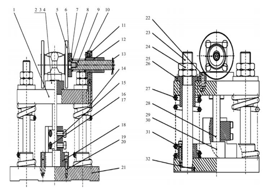
1. Support plates 2. Positioning blocks 3,6,10,14,15,16,19,26,30. Hexagon socket head screws 4. Positioning pins 5. Valve bodies 7. Positioning plates 8. Positioning springs 9. Positioning rods 11. Positioning vertical plates 12.25. Bearings 13. Split pins 17. Slotting blocks 18. Slotting tool holders 20.22. Cylindrical pins 21. Lower support plates 23. Uprights 24. Hexagon thin nuts 27. Support springs 28. Slotting tools 29. Slotting tool support blocks 31. Spring limited blocks 32. Screws
3. Structural characteristics
(1) Versatility
Under the circumstance that the overall structure of the fixture remains unchanged, only by replacing a small number of parts can realize the processing of the wedge guide grooves of a variety of valve bodies; the fixture can be applied to valve bodies with flange or welding ends and non-flange and non-welding ends. As for the existing fixtures, one set of fixtures can only process one type of valve body.
(2) Easy clamping
The clamping and operation of the valve body are simple. The valve body is clamped by the upper end of the clamp body, which is more convenient than the clamping from the lower end.
(3) High accuracy
This fixture has completed the tool setting process when installing the slotting tool and positioning block. During processing, no adjustments are required. It completely avoids not being straight and size deterioration of the guide groove.
(4) Fast processing speed
The processing speed is doubled due to the change of clamping method.
1. Overview
Gate valves are widely used in petrochemical and other pipelines to control the medium in the pipeline. They have the characteristics of small flow resistance, flexible opening and closing, long life, compact structure, safety and reliability. The guide groove on the valve body of forged gate valves is a structure used to restrict the movement direction of the wedge, which ensures that the wedge can only move up and down along the guide groove to realize the purpose of opening and closing of the wedge. A fixture for processing guide grooves of wedges which has high production efficiency, convenient clamping and excellent product quality is introduced in this article.
2. Processing analyses
2.1 Traditional processing methods
The existing method for processing the guide groove of the wedge of the forged steel valve is to clamp the valve body on a special fixture of a slotting machine and process it with a slotting tool. This processing method has low processing efficiency and is time-consuming, labor-intensive for clamping; its product quality and processing speed are greatly affected by the degree of operational proficiency; quality defects such as guide groove deviation and great size deviation are easy to occur, which affects the quality of valve products.
2.2 New processing methods
The guide groove processing fixture for valve bodies is composed of horizontally placed upper support plates, lower support plates and other parts (Figure 1). There are 4 sets of uprights and linear bearings on the relative positions of the upper and lower support plates, and 4 support springs are arranged between the upper and lower support plate. The upright is installed in the counterbore of the lower support plate through a stepped shaft structure, and the upright is fixed on the lower support plate through a set screw to prevent the upright from rotating. A linear bearing is installed on the upper support plate and fixed on the upper support plate by a hexagon socket screw.
A positioning vertical plate is arranged on one side of the upper positioning plate, and a linear bearing is installed on the positioning vertical plate. A set of positioning mechanisms is installed in the linear bearing, and the mechanism includes a positioning plate, a positioning spring, a positioning rod, and a cotter pin for spacing. A positioning block is installed on the upper positioning plate, and the positioning block is fixed on the upper support plate through a cylindrical pin and a hexagon socket screw. A slotting tool holder is arranged on the lower supporting plate, and it is connected with the lower supporting plate through a cylindrical pin and a hexagon socket screw. A slotting tool holder has a square opening matched with the inserting tool. A slotting tool support block with better hardness than the lower support plate is installed in the slotting tool holder. After the slotting tool is inserted in the slotting tool holder, it is fixed on the slotting tool holder by the hexagon socket screw on the side of the slotting tool and the slotting block on the other side.
When using the fixture, the valve body is placed on the positioning block, and the cylindrical boss on the positioning block is matched with the concave part of the valve body cavity. The end surface of the positioning mechanism coincides with the fracture surface of the valve body due to the elastic force of the positioning spring on the positioning vertical plate. The positioning of the valve body on the fixture is ensured by the concave part of the valve body and end surface on one side.
During slotting, the fixture is installed on a press machine, and the upper end of the press machine applies pressure to the valve body. The valve body and the components on the upper support plate move downward under pressure, and the slotting tool enters the valve body for cutting. When the slotting tool moves to the specified position, the press machine starts to move in the reverse direction, and the valve body along with the components on the upper support plate also move in the reverse direction with the press machine because of the elastic force of the support spring, completing the process of retracting the tool. The operation is the same for valve bodies with flange ends or welding ends. When processing valves of different diameters, you only need to replace the matching positioning block and slotting tool, slotting tool block, slotting tool holder, and other parts. The fixture can be used more by replacing a small number of parts.
Fig. 1 Fixtures for processing guide grooves of valve bodies
1. Support plates 2. Positioning blocks 3,6,10,14,15,16,19,26,30. Hexagon socket head screws 4. Positioning pins 5. Valve bodies 7. Positioning plates 8. Positioning springs 9. Positioning rods 11. Positioning vertical plates 12.25. Bearings 13. Split pins 17. Slotting blocks 18. Slotting tool holders 20.22. Cylindrical pins 21. Lower support plates 23. Uprights 24. Hexagon thin nuts 27. Support springs 28. Slotting tools 29. Slotting tool support blocks 31. Spring limited blocks 32. Screws
3. Structural characteristics
(1) Versatility
Under the circumstance that the overall structure of the fixture remains unchanged, only by replacing a small number of parts can realize the processing of the wedge guide grooves of a variety of valve bodies; the fixture can be applied to valve bodies with flange or welding ends and non-flange and non-welding ends. As for the existing fixtures, one set of fixtures can only process one type of valve body.
(2) Easy clamping
The clamping and operation of the valve body are simple. The valve body is clamped by the upper end of the clamp body, which is more convenient than the clamping from the lower end.
(3) High accuracy
This fixture has completed the tool setting process when installing the slotting tool and positioning block. During processing, no adjustments are required. It completely avoids not being straight and size deterioration of the guide groove.
(4) Fast processing speed
The processing speed is doubled due to the change of clamping method.
Next: Stellite Alloy Surfacing Repair Processes of 15CrMo Forged Gate Valves (Part One)
Previous: The Processing of Guide Grooves of Forged Steel Gate Valves' Wedges

News
About Us
Best Categories
Useful Links