Research on Generalization of Forged Steel Hydrogenation Valve Bodies Based on the Finite Element
Research on Generalization of Forged Steel Hydrogenation Valve Bodies Based on the Finite Element
Sep 08, 2021
Abstract: Aiming at the problems of high manufacturing costs and long production cycles of forged steel hydrogenation valve bodies, take two Y-shaped forged steel globe valves with a diameter of 10IN and pressure of 1500LB and 2500LB as an example. Universal and innovative design is carried out for the forged steel valve bodies with the same diameter and different pressure. The finite element analysis software Patran is used for the static analysis, and the stress conditions of the two valve bodies in all directions under the maximum force are obtained, which verifies the rationality and feasibility of the universal design of valve body parts.
The hydrogenation technology is an important measure in the 21st century to effectively utilize petroleum resources and protect the environment to realize the sustainable development of the oil refining industry. In recent years, the hydrogenation technology has continued to develop rapidly in China, and it is extremely urgent to accelerate the nationalization of hydrogenation valves. The valve body is the most critical stress bearing part of the hydrogenation valve. The rationality of its structural design and the reliability of its manufacturing directly determine the domestic production process of the forged steel hydrogenation valve.
The style of the valve body forging structure is the biggest problem encountered in the development of forged steel hydrogenation valves. The multi-directional technology has been applied to the valve body for a long time abroad, but it has only just emerged in China in recent years. It is used for valve bodies with small sizes, and valves above 6 Inches are not available. The manufacturing cost of multi-directional molds is very expensive, and a single valve factory cannot afford excessive mold costs for production with small batches. Therefore, the current domestic hydrogenation valve body forgings mostly adopt semi-free forging. In view of the long production cycle of semi-free forging and the high cost of materials used, it is necessary to study the general design of forged steel valve bodies with the same diameter but different pressure so that the same channel and the outer diameter of the middle cavity can be used for valve bodies with the same diameter but different pressure. Using this design method can realize the generalization of the forging die cavity. When the valve body forgings of different pressure are produced, only the blanking size and the punch pin of the punching need to be changed to obtain formation. This greatly reduces the cost of the mold. Taken a 10 Inches GYPF25BY Y-type forged steel globe valve with pressure of 1500LB and a 10 Inches Y-type forged steel globe valve with pressure of GYPF45BY 2500LB as an example. The wall thickness of the valve body is calculated according to the standard "Flanged, Threaded and Welded Valves". The relationship between the inner diameter and outer diameter of the valve body is studied. An innovative design is performed for the outer diameter of the channel and middle cavity. Patran is used to analyze the force and deformation of the valve body when it is put into use and to verify the rationality and feasibility of the generalized design of valve body parts.
1. Universal design of valve bodies
1.1 Basic parameters
The type of valve: Y-shaped forged steel globe valves
Technical parameters: The nominal diameter is 10IN; the nominal pressure is 2500LB (42MPa) and 4500LB (76MPa).
1.2 Determination of the wall thickness of the valve body
According to Appendix VI Basic Formulas for Minimum Wall Thicknesses of ASME B16.34 -2013 mandatory standard, calculation data of wall thickness of 10" GYPF25BY and 10" GYPF45BY forged steel globe valve bodies are shown in Table 1 and Table 2.
Table 1 Calculated values of body wall thickness of 10IN GY PF25BY forged steel globe valves mm
| Parameters | Formulas or descriptions | Calculated data |
| Diameter of Channels d1 | Checking ASME B16.34-2013 | 184 |
| Maximum diameters of middle cavities d2 | Design | 278 |
| Calculated valve diameters d | Taking the greater value between d1 and (d2 | 185.3 |
| Calculated wall thickness t | 0.34091×d+2.54 | 65.7 |
| Designed wall thickness ts | Determination by design | 68.5 |
Table 2 Calculated values of body wall thickness of 10IN GYPF45BY forged steel globe valves mm
| Parameters | Formulas or descriptions | Calculated data |
| Diameter of Channels d1 | Checking ASME B16.34-2013 | 127 |
| Maximum diameters of middle cavities d2 | Design | 165.8 |
| Calculated valve diameters d | Taking the greater value between d1 and d2 | 110.5 |
| Calculated wall thickness t | 0.34091×d+2.54 | 89.26 |
| Designed wall thickness ts | Determination by design | 103.5 |
1.3 Design of the outer diameter of the valve body channel and the middle cavity
According to the design size of the valve body's wall thickness, the outer diameter of the valve body channel and the middle cavity is determined. Unified outer diameters of the 10" GYPF25BY and GY PF45BY valve body channels and middle cavities are obtained by considering the feasibility and economy of valve body forging and based on long-term design experience. The specific dimensions are shown in Table 3.
2. Strength analysis of the finite element of the valve body
2.1 Strength analysis of 10 Inches GYPF25BY valve bodies
The 3D model of the 10IN GYPF25BY valve body is shown in Figure 1.
Table 3 Design of outer diameters of valve body channels and that of middle cavities of 10IN GYPF25BY and 10IN GYPF45BY mm
| Types | Parameters | Calculation formulas | Theoretical calculation values | Design values |
| 10"G YPF25BY | Outer diameters of channels D1 | d1+2ts | 321 | 334 |
| Outer diameters of middle cavity D2 | d2+2ts | 415 | 415 | |
| 10"G YPF45BY | Outer diameters of channels D1 | d1+2ts | 334 | 334 |
| Outer diameters of middle cavity D2 | d2+2ts | 372.8 | 415 |
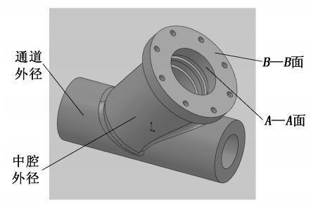
Figure 1 10IN GYPF25BY three-dimensional models of valve bodies
The valve body's pressure is 42MPa; the valve body's material is ASTM A105, and the material yield strength is greater than and equal to 250MPa. The yield strength in the qualified supplier's material report is 360MPa; the Poisson's ratio is 0.30, and the elastic modulus is 202GPa. Tensile strength is greater than and equal to 485MPa. The boundary conditions are set as follows during the analysis: ①The two ports of the channel are welded with pipeline with an infinite length and dimensions of Φ73 mm and Φ4177 mm. ②The self-sealing part of the A-A surface is subjected to internal pressure of 42MPa, and the radial component force generated by the self-sealing of the bonnet is 4636.6kN; the specific pressure of the self-tightening sealing ring to the valve body is 212.4MPa. ③The axial force and pre-tightening force caused by the internal pressure on the B-B surface is 2664.7kN; ④8-1 1/2-8UN (American unified threads) the force on the thread is 1073.6kN when the valve disc is closed.
The valve body is forging with a round hole, and each connection has transition fillets and chamfers. Its structure is relatively complicated. In order to facilitate the calculation, the three-dimensional model of the valve body is appropriately simplified. Create meshes in the model in the MSC. Patran software, load the displacement and pressure constraints according to the boundary conditions; enter the Poisson's ratio and the elastic modulus of the valve body, and then use the Nastran solver for the linear solution. A stress cloud diagram of a 10" GYPF25BY valve body can be obtained, as shown in picture 2.
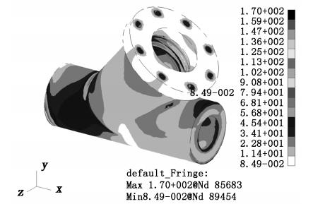
Figure 2 10IN deformation cloud diagrams of GYPF25BY valve bodies
2.2 Strength analysis of 10" GYPF45BY valve bodies
The three-dimensional model of the 10" GYPF45BY valve body is shown in Figure 3. The known valve body pressure is 76MPa, valve body material 304, material yield strength greater than and equal to 235MPa, yield strength in the qualified supplier's material report 323MPa, tensile strength greater than and equal to 515MPa, elastic modulus 195GPa, and Poisson's ratio 0.31.
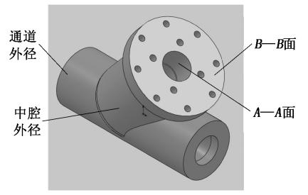
Figure 3 The three-dimensional model of the 10IN GY PF45BY valve body
The boundary conditions are set as follows during the analysis: ①The size of the two-port welded infinite pipe of the channel is Φ273 mm and 169 mm. ②The self-sealing part of A-A is subjected to internal pressure of 76MPa. ③4-1 5/8-8UN thread is compressed by the packing and the force is 1165.4kN. ④The force when the valve disc is closed at the 8-1 1/2-8UN thread is 1153kN. Using the same solution steps as 10"GYPF25BY, the stress cloud diagram of the 10'GY PF45BY valve body is shown in Figure 4.
3. The analysis of the result
It can be seen from Figure 2 that the maximum stress that the valve body bears during operation is 170MPa, which is smaller than the yield limit of 250MPa for the material used for the part, and far less than the yield strength of 360MPa in the qualified supplier's material report; the safety factor is 2.1. The stress of most parts is less than 102MPa, so it can be said that the structure of this valve body is safe and reliable, which can withstand external loads during work. It can be seen from Figure 4 that the maximum stress the valve body borne during operation is 222MPa, which is smaller than the yield limit of the material used in the part, that is, 235MPa, and is less than the yield strength of 360MPa in the qualified supplier's material report; the safety factor is 1.5. The stress is less than 111MPa, so it can be said that the structure of the valve body is safe and reliable, and can withstand external loads during operation.
Previous: Design and Research of Forged Slab Gate Valves without Welding Seams

News
About Us
Best Categories
Useful Links