High-Pressure Forged Steel Slab Gate Valves (Part One)
High-Pressure Forged Steel Slab Gate Valves (Part One)
Nov 18, 2020
Abstract: This article introduces the main performance, DBB function and working principle of the high-pressure forged steel slab gate valve, and analyzes its structural characteristics and the key points of processing technology.
The slab gate valve is a sliding valve with the parallel wedge disc as the closing part. It is mainly used for oil and natural gas pipelines. It is inconvenient to manage and maintain the valve, because it is installed in an open field. The medium is a combustible medium such as oil and gas. Once leakage occurs, it's not easy to detect the leakage. High temperatures can easily cause fire. Therefore, there are strict requirements for the sealing performance of the valve. At present, the slab gate valves on the market are basically made of cast steel. With the development of science and technology, higher requirements are put forward for the safety and reliability of valve materials. In order to solve the problem of unreliable sealing and short service life of the slab gate valve, this article introduces a high-pressure forged steel slab gate valve with a double block and bleed (DBB) function.
Main performance
Applicable medium: Oil or natural gas
Design temperature: 121℃
Nominal pressure: PN160
Nominal size: DN450
Body material: A105
Sealing surface: A combination of Non-metal and metal
Structure type: Single wedge discs with diversion holes
Driving mode: Bevel gear drives
Working principles
The bevel gear drive mechanism drives the valve stem through the valve stem nut, and then drives the wedge disc to open or close. There is an inverted sealing structure on the head of the valve stem to control the opening position of the wedge disc. When the valve is fully opened, the diversion hole of the wedge disc just coincides with the center line of the inner hole of the valve seat. The limit mechanism at the tail of the valve stem is used to control the closing position of the wedge disc. The valve has a two-way sealing structure. The valve seat is equipped with a spring to provide sealing pre-tightening force. The valve cavity is equipped with a discharge and draining system. After proper discharge and the valve is fully closed, there is no leakage at the valve seat position, that is, the valve has double block and bleed (DBB) function.
Structural features and key points of processing technology
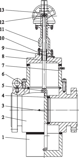
The high-pressure forged steel slab gate valve is mainly composed of the valve body, wedge disc, valve seat, valve stem, packing, bracket and bevel gear transmission mechanism. See the Figure 1. The high-pressure forged steel slab gate valve has the following structural characteristics and key points of processing technology:
Figure 1 The high-pressure forged steel slab gate valve

1. The valve body bottom cover 2. The valve body 3. The wedge disc 4. The valve seat 5. The valve stem 6. The octagonal gasket 7. The lower part of the bonnet 8. The upper part of the bonnet 9. The grease injection valve 10. The packing 11. The bracket 12. The limiting mechanism 13. Bevel gear transmission mechanism
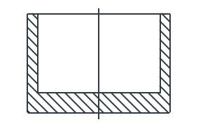
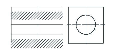
(1) The valve body is made of A105 forging material. Currently, there is no multi-directional die forging hammer, and only free forging can be used. The valve body flange and the valve body are integrally forged, and the bottom cover of the valve body (Figure 2) and the valve body (Figure 3 ) are connected by butt welding. The inner cavity and shape of the bottom cover of the valve body have circular structures, and the depth of the inner cavity should ensure that the wedge disc is completely closed without interference. The valve body forged part has a rectangular structure with a through hole in the middle, and the rest are solid. The length of the rectangular corresponds to the structural length of the valve body. The width and thickness of the rectangular are slightly greater than the outer diameter of the flange. The size of the middle through hole is the flow diameter of the valve body. See the Figure 4.
Figure 2 The forged body bottom cover part

Figure 3 The forged valve body

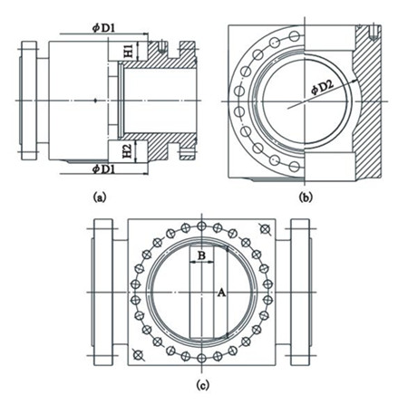
The difficulty in valve body processing is the middle cavity. When processing the valve, first machine the upper end of the valve body ΦD1 with depth H1 and the lower end of the valve body ΦD1 with depth H2, and then machine the valve seat hole and the process groove ΦD2 with width B from the flow passage. Finally machine the square groove A X B with a facing machine. The width B must satisfy the assembly space of two valve seats and the wedge disc during assembly. The length A should be 2mm longer than the width of the wedge disc and greater than the diameter of the valve seat. This design can not only ensure that the wedge disc and the valve seat are installed in the valve body, but also guide both sides of the wedge disc. ΦD1 should be bigger than √A2+B2 and ΦD2 is about 1.25 times length of A. The purpose of the process groove is to remove the machining allowance of the square groove A X B as much as possible, and to ensure that the wall thickness of the valve body meets the requirements at the same time.
Figure 4 Valve body processing

(a) The front view (b) The left view (c) The top view
(2)The bonnet is made of A105 by forging. The bonnet is formed by butt welding between the upper part of the bonnet and the lower part of the bonnet, which can save materials to the greatest extent and reduce the production cost of the valve. The inner cavity and shape of the valve cover have circular structure. The inner cavity diameter is slightly bigger than √a2+b2. A is the width of the wedge disc, and b is the thickness of the wedge disc. When the wedge disc is opened, it will not be interfered by the bonnet. The bonnet has a guiding role for the four edges of the wedge discs.

1. The valve body bottom cover 2. The valve body 3. The wedge disc 4. The valve seat 5. The valve stem 6. The octagonal gasket 7. The lower part of the bonnet 8. The upper part of the bonnet 9. The grease injection valve 10. The packing 11. The bracket 12. The limiting mechanism 13. Bevel gear transmission mechanism
(1) The valve body is made of A105 forging material. Currently, there is no multi-directional die forging hammer, and only free forging can be used. The valve body flange and the valve body are integrally forged, and the bottom cover of the valve body (Figure 2) and the valve body (Figure 3 ) are connected by butt welding. The inner cavity and shape of the bottom cover of the valve body have circular structures, and the depth of the inner cavity should ensure that the wedge disc is completely closed without interference. The valve body forged part has a rectangular structure with a through hole in the middle, and the rest are solid. The length of the rectangular corresponds to the structural length of the valve body. The width and thickness of the rectangular are slightly greater than the outer diameter of the flange. The size of the middle through hole is the flow diameter of the valve body. See the Figure 4.
Figure 2 The forged body bottom cover part

Figure 3 The forged valve body

The difficulty in valve body processing is the middle cavity. When processing the valve, first machine the upper end of the valve body ΦD1 with depth H1 and the lower end of the valve body ΦD1 with depth H2, and then machine the valve seat hole and the process groove ΦD2 with width B from the flow passage. Finally machine the square groove A X B with a facing machine. The width B must satisfy the assembly space of two valve seats and the wedge disc during assembly. The length A should be 2mm longer than the width of the wedge disc and greater than the diameter of the valve seat. This design can not only ensure that the wedge disc and the valve seat are installed in the valve body, but also guide both sides of the wedge disc. ΦD1 should be bigger than √A2+B2 and ΦD2 is about 1.25 times length of A. The purpose of the process groove is to remove the machining allowance of the square groove A X B as much as possible, and to ensure that the wall thickness of the valve body meets the requirements at the same time.
Figure 4 Valve body processing

(a) The front view (b) The left view (c) The top view
(2)The bonnet is made of A105 by forging. The bonnet is formed by butt welding between the upper part of the bonnet and the lower part of the bonnet, which can save materials to the greatest extent and reduce the production cost of the valve. The inner cavity and shape of the valve cover have circular structure. The inner cavity diameter is slightly bigger than √a2+b2. A is the width of the wedge disc, and b is the thickness of the wedge disc. When the wedge disc is opened, it will not be interfered by the bonnet. The bonnet has a guiding role for the four edges of the wedge discs.
Next: High-Pressure Forged Steel Slab Gate Valves (Part Two)
Previous: Reasons for the Forced Seal of the Stainless Steel Forged Steel Valve
News
About Us
Best Categories
Useful Links
