High-Pressure Forged Steel Slab Gate Valves (Part Two)
High-Pressure Forged Steel Slab Gate Valves (Part Two)
Nov 30, 2020
(3) The sealing surface of the wedge disc is welded by STL hard alloys. After fine finishing and grinding of the valve seat, the surface roughness Ra value is 0.4μm, and the parallelism of both sides is 0.08mm.
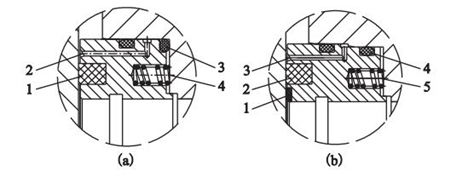
(4) The common structure of the valve seat is shown in the Figure 5(a). The disadvantage of this structure is that the non-metallic sealing ring is prone to leakage after damage, and only the valve seat at the outlet end is sealed, that is, the wedge disc is pushed to the valve seat outlet end by the force of the medium to realize the sealing function of the soft sealing ring and the O-ring on the end face of the valve seat. However, this valve has been improved on this basis, as shown in the Figure 5 (b). The sealing surface of the valve seat is composed of an inner ring and an outer ring. The inner ring is build up welded by STL hard alloys. The two rings can meet the sealing requirements under high pressure conditions, after fine finishing and grinding to match the wedge disc. The outer ring of the valve seat is inlaid with a non-metallic sealing ring, and there is a grease injection hole outside the non-metallic sealing ring to meet the emergency grease injection sealing function and meet the triple sealing requirements. The valve seat is provided with a spring to provide sealing pre-tightening force; the outer circle of the valve seat is provided with two O-rings, and the valve cavity is equipped with a discharge and draining system. After proper discharge and the valve is fully closed, no leakage occurs at both ends of the valve seat, that is, the valve has a double block and bleed (DBB) function.
(4) The common structure of the valve seat is shown in the Figure 5(a). The disadvantage of this structure is that the non-metallic sealing ring is prone to leakage after damage, and only the valve seat at the outlet end is sealed, that is, the wedge disc is pushed to the valve seat outlet end by the force of the medium to realize the sealing function of the soft sealing ring and the O-ring on the end face of the valve seat. However, this valve has been improved on this basis, as shown in the Figure 5 (b). The sealing surface of the valve seat is composed of an inner ring and an outer ring. The inner ring is build up welded by STL hard alloys. The two rings can meet the sealing requirements under high pressure conditions, after fine finishing and grinding to match the wedge disc. The outer ring of the valve seat is inlaid with a non-metallic sealing ring, and there is a grease injection hole outside the non-metallic sealing ring to meet the emergency grease injection sealing function and meet the triple sealing requirements. The valve seat is provided with a spring to provide sealing pre-tightening force; the outer circle of the valve seat is provided with two O-rings, and the valve cavity is equipped with a discharge and draining system. After proper discharge and the valve is fully closed, no leakage occurs at both ends of the valve seat, that is, the valve has a double block and bleed (DBB) function.
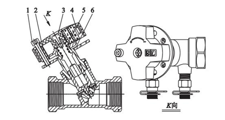
1. Hexagon bolts 2. Inserts 3. Screws 4. Handwheel parts 5. Snap rings 6. Locking plates
The locking screw can be a specific hexagonal screw, preventing the ordinary hexagonal wrench from opening to adjust the opening height of the valve clack and changing the control flow of the channel.
Locking plates
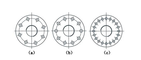
(a) 8 holes (b) 10 holes (c) 20 holes
After the structure of the balanced valve is improved, a fixed locking plate is set on the valve bonnet, and a locking screw is set on the hand wheel. After the opening height of the balanced valve is set. Inserted the head of the locking screw into the corresponding locking hole on the locking plate by a tool. Make the positioning of the valve fixed. If you want to adjust the opening height of the balanced valve, you must use a tool to release the hand wheel and then turn the hand wheel to adjust the valve so as to prevent the flow balance from rotating the handwheel at will during use. The improved balance valve has the characteristics of simple structures, low costs, easy adjustment and use.
(5) Coupled with a grease injection valve, the packing box adopts V-shaped packing with a V-shaped spacer ring in the middle to meet the low leakage requirements for the valve. The valve has an upper sealing function. The pacing box adopts the form of the packing gland. See the Figure 6.
(a) Structure of improved front valve seats (b) Structure of improved back valve seats
Valve seat structure
The locking screw can be a specific hexagonal screw, preventing the ordinary hexagonal wrench from opening to adjust the opening height of the valve clack and changing the control flow of the channel.
Locking plates
(a) 8 holes (b) 10 holes (c) 20 holes
After the structure of the balanced valve is improved, a fixed locking plate is set on the valve bonnet, and a locking screw is set on the hand wheel. After the opening height of the balanced valve is set. Inserted the head of the locking screw into the corresponding locking hole on the locking plate by a tool. Make the positioning of the valve fixed. If you want to adjust the opening height of the balanced valve, you must use a tool to release the hand wheel and then turn the hand wheel to adjust the valve so as to prevent the flow balance from rotating the handwheel at will during use. The improved balance valve has the characteristics of simple structures, low costs, easy adjustment and use.
(5) Coupled with a grease injection valve, the packing box adopts V-shaped packing with a V-shaped spacer ring in the middle to meet the low leakage requirements for the valve. The valve has an upper sealing function. The pacing box adopts the form of the packing gland. See the Figure 6.
(a) Structure of improved front valve seats (b) Structure of improved back valve seats
Valve seat structure
(a) Soft seal rings 2. Grease holes 3. O-rings 4. Springs (b) STL hard alloys 2. Non-metallic seal rings 3. Grease holes 4. O-rings 5. Springs
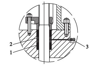
1. V-shaped packing 2. V-shaped spacer rings 3. Grease injection valves
Packing box structure
(6) Limiting mechanism is at the tail of the valve stem (Figure 7). The limited block has a trapezoidal threaded inner hole, which is screwed on the tail of the valve stem, and then compressed with studs and nuts. When the wedge disc is closed, the limited block gradually moves downward with the valve stem. When the limited block touches the valve stem nut, the wedge disc is just at the fully closed position. Because of the high strength of the trapezoidal thread and the large transmission torque, the limited block is resistant to impact and has good positioning accuracy. An observation hole is drilled on the valve stem cover, and the stud also has an indication of the opening and closing position of the wedge disc.
The limiting mechanism
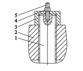
1. Valve stems 2. Stem nuts 3. Limited blocks 4. Nuts 5. Studs
Conclusion
Because of the high density, good plasticity and toughness of the internal structure of the forging material, the high-pressure forged steel slab gate valve effectively improves the quality of the slab gate valve, and can be operated safely for high-pressure oil and natural gas pipelines for a long time. The successful development of the high-pressure forged steel slab gate valve improves the overall sealing performance and the service life of the valve, and effectively reduces the field management and maintenance costs of the pipeline.
(6) Limiting mechanism is at the tail of the valve stem (Figure 7). The limited block has a trapezoidal threaded inner hole, which is screwed on the tail of the valve stem, and then compressed with studs and nuts. When the wedge disc is closed, the limited block gradually moves downward with the valve stem. When the limited block touches the valve stem nut, the wedge disc is just at the fully closed position. Because of the high strength of the trapezoidal thread and the large transmission torque, the limited block is resistant to impact and has good positioning accuracy. An observation hole is drilled on the valve stem cover, and the stud also has an indication of the opening and closing position of the wedge disc.
The limiting mechanism
1. Valve stems 2. Stem nuts 3. Limited blocks 4. Nuts 5. Studs
Conclusion
Because of the high density, good plasticity and toughness of the internal structure of the forging material, the high-pressure forged steel slab gate valve effectively improves the quality of the slab gate valve, and can be operated safely for high-pressure oil and natural gas pipelines for a long time. The successful development of the high-pressure forged steel slab gate valve improves the overall sealing performance and the service life of the valve, and effectively reduces the field management and maintenance costs of the pipeline.
Next: Features of Forged Steel Cryogenic Globe Valves
Previous: High-Pressure Forged Steel Slab Gate Valves (Part One)

News
About Us
Best Categories
Useful Links