Design of two-piece forged titanium ball valves with small diameters
Design of two-piece forged titanium ball valves with small diameters
Feb 15, 2023
Abstract
The design process of the small-diameter two-piece forged titanium ball valves is introduced, the overall material consumption of the valve can be reduced and the cost can be saved by optimizing the structure of the valve body and bonnet.
There is rich titanium in the earth's crust, but its activity is high. It takes a lot of energy to dissociate titanium from titanium ore and smelt it into sponge titanium. The melting point of pure titanium is as high as 1 668±4°C, and it is easy to react with oxygen. Therefore, it must be smelted under a vacuum. The cost of producing titanium is high, which leads to its relatively high market price, and its application is limited. Titanium is widely used in aerospace because of its low density and high specific strength. Titanium has excellent corrosion resistance and is mostly used in the petrochemical industry (TA1, TA2, TA3). There are more and more chemical products with good corrosion due to the development of industry, and the demand for titanium valves is increasing, such as titanium ball valves, check valves, globe valves, butterfly valves, gate valves and plug valves, etc. Among these different types of valves, titanium ball valves are the most common. Ball valves have the advantages of rapid opening and closing, small fluid resistance, good sealing, compact structure, easy operation and maintenance, and are widely used in the industry.
Structural optimization
For each type of valve, the performance indicators and service life of the valve must meet the user's requirements, and at the same time, its cost must also be considered, especially for valves made of some precious metal. The design is also an effective way to reduce costs. The following will take the small-diameter two-piece forged titanium ball valve as an example to optimize the structure of the valve body and bonnet; compare it before and after optimization, and came to conclusions with data.
1. Before optimization
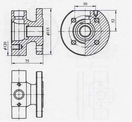
The schematic diagram of the valve body’s structure before the optimization is shown in Figure 1.

Figure 1 The schematic diagram of the valve body’s structure
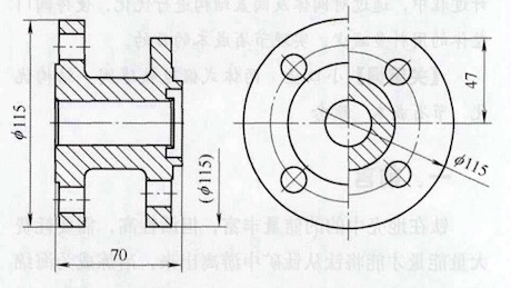
It can be seen from the given parameters that the nominal diameter of the valve is DN25, the nominal pressure is PN16, the flange is in accordance with the standard GB/T9113-2o10 (integral steel pipe flange), and the sealing surface is RF (raised surface). The diameter of the outer circle of the flange is 115mm from the relevant standards, and the two bolt holes marked with a distance of 50mm in the left view are used for installing the packing pressure plate. This distance has been adjusted to the proper position according to the valve stem size, packing size and packing gland size. The outer circle diameter of the middle cavity of the valve body is designed to be 120mm, and the total length of the valve body is 75mm. The schematic diagram of the valve bonnet structure is shown in Figure 2.

Figure 2 Optimized front bonnet structure
There is a matching relationship between the valve bonnet and the valve body, and they are connected by fasteners during assembly. The outer diameter of the connecting part between the valve bonnet and the valve body is designed to be 120mm, and the total length of the valve bonnet is 70mm.
2. After optimization
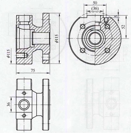
The simplified diagram of the valve body’s structure after optimization is shown in Figure 3.

Figure 3 The schematic diagram of the optimized valve body’s structure
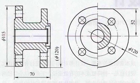
On the premise of not affecting the overall strength of the valve, the diameter of the outer circle of the valve body cavity is reduced from 120mm to l15mm, so that it is the same as the outer circle size of the flanges at both ends, and the size of the blank can be based on the outer circle size of the connecting flange (l15mm ) and given with a certain margin. If the dimension 52mm of the left view in Figure 3 is not changed, the bolt hole for installing the packing plate will be located at the junction of the upper plane and the outer circular arc surface of the middle cavity, which will bring difficulties to the processing and may lead to the accuracy of the bolt hole position. This is not allowed in the design principles, and should be avoided during design. Therefore, in the upper end plane of the left view, take the size of 36mm as the benchmark, lower the table surface by 5mm to form a boss and a new plane for the machining the bolt hole, so that the bolt hole is completely formed in the plane area. It is worth noting that the outer contour of the formed boss must be within the range of the reduced outer diameter of the cavity (115mm), that is, within the range of the dotted line in the figure, to facilitate the subsequent processing of the boss. The schematic diagram of the optimized bonnet structure is shown in Figure 4.

Figure 4 Optimized bonnet structure
Considering the matching relationship between the bonnet and the valve body and the overall aesthetics after assembly, reduce the diameter of the outer circle at the connection between the bonnet and the valve body from 120mm to 115mm, and adjust the size from 52mm to 47mm.
3. Comparison
The following table shows the changes in relevant parameters before and after optimization.
Relevant parameters before and after optimization
The design process of the small-diameter two-piece forged titanium ball valves is introduced, the overall material consumption of the valve can be reduced and the cost can be saved by optimizing the structure of the valve body and bonnet.
There is rich titanium in the earth's crust, but its activity is high. It takes a lot of energy to dissociate titanium from titanium ore and smelt it into sponge titanium. The melting point of pure titanium is as high as 1 668±4°C, and it is easy to react with oxygen. Therefore, it must be smelted under a vacuum. The cost of producing titanium is high, which leads to its relatively high market price, and its application is limited. Titanium is widely used in aerospace because of its low density and high specific strength. Titanium has excellent corrosion resistance and is mostly used in the petrochemical industry (TA1, TA2, TA3). There are more and more chemical products with good corrosion due to the development of industry, and the demand for titanium valves is increasing, such as titanium ball valves, check valves, globe valves, butterfly valves, gate valves and plug valves, etc. Among these different types of valves, titanium ball valves are the most common. Ball valves have the advantages of rapid opening and closing, small fluid resistance, good sealing, compact structure, easy operation and maintenance, and are widely used in the industry.
Structural optimization
For each type of valve, the performance indicators and service life of the valve must meet the user's requirements, and at the same time, its cost must also be considered, especially for valves made of some precious metal. The design is also an effective way to reduce costs. The following will take the small-diameter two-piece forged titanium ball valve as an example to optimize the structure of the valve body and bonnet; compare it before and after optimization, and came to conclusions with data.
1. Before optimization
The schematic diagram of the valve body’s structure before the optimization is shown in Figure 1.

Figure 1 The schematic diagram of the valve body’s structure
It can be seen from the given parameters that the nominal diameter of the valve is DN25, the nominal pressure is PN16, the flange is in accordance with the standard GB/T9113-2o10 (integral steel pipe flange), and the sealing surface is RF (raised surface). The diameter of the outer circle of the flange is 115mm from the relevant standards, and the two bolt holes marked with a distance of 50mm in the left view are used for installing the packing pressure plate. This distance has been adjusted to the proper position according to the valve stem size, packing size and packing gland size. The outer circle diameter of the middle cavity of the valve body is designed to be 120mm, and the total length of the valve body is 75mm. The schematic diagram of the valve bonnet structure is shown in Figure 2.

Figure 2 Optimized front bonnet structure
There is a matching relationship between the valve bonnet and the valve body, and they are connected by fasteners during assembly. The outer diameter of the connecting part between the valve bonnet and the valve body is designed to be 120mm, and the total length of the valve bonnet is 70mm.
2. After optimization
The simplified diagram of the valve body’s structure after optimization is shown in Figure 3.

Figure 3 The schematic diagram of the optimized valve body’s structure
On the premise of not affecting the overall strength of the valve, the diameter of the outer circle of the valve body cavity is reduced from 120mm to l15mm, so that it is the same as the outer circle size of the flanges at both ends, and the size of the blank can be based on the outer circle size of the connecting flange (l15mm ) and given with a certain margin. If the dimension 52mm of the left view in Figure 3 is not changed, the bolt hole for installing the packing plate will be located at the junction of the upper plane and the outer circular arc surface of the middle cavity, which will bring difficulties to the processing and may lead to the accuracy of the bolt hole position. This is not allowed in the design principles, and should be avoided during design. Therefore, in the upper end plane of the left view, take the size of 36mm as the benchmark, lower the table surface by 5mm to form a boss and a new plane for the machining the bolt hole, so that the bolt hole is completely formed in the plane area. It is worth noting that the outer contour of the formed boss must be within the range of the reduced outer diameter of the cavity (115mm), that is, within the range of the dotted line in the figure, to facilitate the subsequent processing of the boss. The schematic diagram of the optimized bonnet structure is shown in Figure 4.

Figure 4 Optimized bonnet structure
Considering the matching relationship between the bonnet and the valve body and the overall aesthetics after assembly, reduce the diameter of the outer circle at the connection between the bonnet and the valve body from 120mm to 115mm, and adjust the size from 52mm to 47mm.
3. Comparison
The following table shows the changes in relevant parameters before and after optimization.
Relevant parameters before and after optimization
| Items | Maximum diameter/mm | blank size/mm | TA2 density/ (g/mm3) | Weights of blanks/kg | |
| Before optimization | Valve bodies | 120 | 129 × 84 | 0.0045 | 4.940 |
| Valve bonnets | 120 | 129 × 79 | 4.646 | ||
| After optimization | Valve bodies | 115 | 123 × 83 | 4.438 | |
| Valve bonnets | 115 | 123 × 78 | 4.171 |
It can be seen from the above table that the weight of the forging blank of the optimized valve body is reduced from the original 4.94kg to 4.438kg per set, and the reduction is 0.502kg per set. The weight of the forging blank is reduced from the original 4.646kg per set to 4.171kg per set; the reduction is 0.475kg per set, and the total material saving of the two is 0.977kg per set. In recent years, the enterprise has contracted about 200 units of titanium ball valves of this specification. The material costs of 23448RMB can be saved for the enterprise based on the current TA2 market price of about 120 RMB per kg.
4. Conclusion
The above optimization method is mostly used when the outer circle of the inner cavity of the valve body is larger than the outer circle of the connecting flange at the end. Of course, it can also be used in the design of ball valves with other diameters and pressure when conditions permit. The material can be stainless steel, Hastelloy, zirconium, titanium and nickel-based alloys. This kind of optimization seems trivial, but there are unexpected effects, especially for some precious metals, the cost savings are quite good. The method of optimization is not limited to this one, as long as you pay more attention to your work, you will find many improvements. Designers should be attached to this design concept and truly reflect years of design experience in product design.
Next: Structural Design of Hydrogenation Valve Bodies
Previous: The Sealing of Fully Welded Forged Ball Valves for Natural Gas Pipelines (Part two)
News
About Us
Best Categories
Useful Links