Test Results of Forging Medium and High-pressure Valve Bonnets
Test Results of Forging Medium and High-pressure Valve Bonnets
Feb 08, 2024
4. Analysis of test results
(1) The problem of thin forging at the top: When the thickness of the blank is certain, it is possible to make the top size of the workpiece thinner by forging. Under our experimental conditions, when the thickness of the blank is less than 6 to 7mm, thin forging will be difficult. For the pre-forged thin bad material, place it on the forming die. On the one hand, the workpiece is thin and heats up quickly; on the other hand, it is in contact with the mold at a lower temperature, because the heat transfer and cooling speed are faster; in the forging process, the upper mold finally touches the top, which increases the heat dissipation time. These reasons cause the temperature of the billet to drop and the deformation tension to increase. In addition, after the lower flash is formed, it is very unlikely that the upper and lower molds will touch each other at the top, so the thickness of the top will naturally remain unchanged. Therefore, for forgings that require thinner top dimensions, only by pre-forging and bending during forming can we obtain better finished products.
(1) The problem of thin forging at the top: When the thickness of the blank is certain, it is possible to make the top size of the workpiece thinner by forging. Under our experimental conditions, when the thickness of the blank is less than 6 to 7mm, thin forging will be difficult. For the pre-forged thin bad material, place it on the forming die. On the one hand, the workpiece is thin and heats up quickly; on the other hand, it is in contact with the mold at a lower temperature, because the heat transfer and cooling speed are faster; in the forging process, the upper mold finally touches the top, which increases the heat dissipation time. These reasons cause the temperature of the billet to drop and the deformation tension to increase. In addition, after the lower flash is formed, it is very unlikely that the upper and lower molds will touch each other at the top, so the thickness of the top will naturally remain unchanged. Therefore, for forgings that require thinner top dimensions, only by pre-forging and bending during forming can we obtain better finished products.
(2) Since the rounded corner part of the forged valve is hot forged and bent, the bend is subject to tensile force; since the cylindrical part is deep, the cylindrical part is formed by impact stretching in the forging process, and the tensile force is greater. Therefore, it is easier to understand when thinning occurs. Bending and impact stretching are performed in sequence. When initially bending, the rounded corners become thinner, and the whole body is stretched due to impact. For plastic deformation, the lower part of the tube undergoes greater tensile deformation than the upper part of the tube, so the wall of the lower part of the tube becomes thinner and bigger than the upper part of the tube. According to the above situation, in order to obtain forgings with equal thickness, the blank near the rounded corners should be thickened to compensate for the wall thinning during bending and tension. The wall thickness reduction at the connection between the barrel and the flange is also caused by bending and stretching. However, when there is enough material, after the flash is formed, the metal will flow back to make up for the thinned part in the forging process. It can be seen from the above situation that when the ratio of h/H is small, the thicker parts bend first and become thinner at the same time in the forging process. When the top metal is bent, the metal flow will be greater, and the barrel will bear greater tensile force. At this time, the thinned and bent part will easily crack.
(3) When the h/H ratio is too great, bending takes up a larger proportion than drawing, and the top is formed last, where the resistance is the smallest. When the lower flash is formed, part of the metal will flow into the mold cavity. Metal naturally piles toward the rounded corners where resistance is least, forming folds there. Therefore, if you want to obtain a well-formed workpiece, the proportion of bending deformation in the forming process should not be too great.
5. Conclusion
For this type of forging, it is more advantageous to use a forming method that combines top bending with barrel impact stretching. In order to adapt to this forming method, the ratio of h/H is preferably around 1.33. The thinner the middle is and the higher the barrel is, the greater the h/H ratio becomes. When making the blank, the blank is shaped into a shape that is thin in the middle and thick around the edges, which is beneficial to forming. In order to obtain a workpiece close to the same thickness, it is advantageous to forge the thin middle part into a gradually thicker part.
6. Specific applications
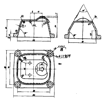
The modified valve bonnet of the steam trap imported from Canada by Dalian High-pressure Valve Factory is shown in Figure 4, which belongs to this type of forgings. The flange part is rectangular with a thickness of 10mm, and the thickness of the top and cylindrical parts is 3mm. The ratio of B/b is 3.33, and the maximum depth of the barrel is 40mm.

Figure 4 The drawing for the modified valve bonnet
Requirements
- Forging fillets not noted are determined by the mold design.
- The size deviation from flange surface to surface is 0.5mm.
- Parting offset: 0.5mm
- Residual flash: 0.5mm
- Vertical size tolerance: +-0.5mm
- Normalizing treatment of forgings
- Phosphating after heat treatment
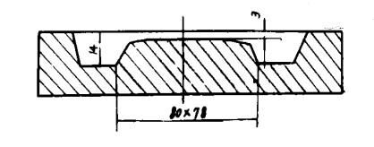
In addition to the characteristics of this type of forging, the valve bonnet also has a small thickness of only 3mm. We designed the mold based on the results of the above experiments. The design of the final forging die or die chamber is the same as the general die design. The key lies in the design of the blanking mold or blanking die chamber. We adopted the h/H ratio of 1.33 based on the above experimental conclusions and the blank is designed as shown in Figure 5.

Figure 5 The drawing for the blank making mold
In the trial production process, the smaller the h/H value was, the cracking occurred at the corner of the barrel. The smaller the h/H value was, the greater the crack was. If the h/H value is too great, folding will appear in the top four corners. Folding also occurred at one corner, two corners, and three corners due to the skewed placement. This also completely confirms the aforementioned experimental results. The processes of this forging are blanking, flattening, billet making, final forging, trimming and correction. Use a 560kg air hammer to forge. After the piece was forged, if 3% of the sample’s thickness error was within the range of about 0.2mm, it could meet the technical requirements of the factory.
Next: Causes and Solutions of Rusting in High-Pressure Ball Valves
Previous: Correct Installation of Forged Steel Check Valves
News
About Us
Best Categories
Useful Links