Temperature Field Calculation & Thermo-solid Coupling Analysis of High-temperature Forged Gate Valves (Part Two)
Temperature Field Calculation & Thermo-solid Coupling Analysis of High-temperature Forged Gate Valves (Part Two)
Oct 10, 2021
3. The calculation of the temperature field of the gate valve under high-temperature conditions
3.1 Boundary conditions and loads
The calculation of the temperature field of the gate valve is conducted by the function of the thermal analysis in Ansys. Ansys thermal analysis is divided into steady-state thermal analysis and transient thermal analysis. Steady-state heat transfer means that the temperature of the system does not change with time, while transient heat transfer is that the temperature of the system changes significantly with time.
In this article, the steady-state thermal analysis is used, considering that the thermal conductivity, specific heat capacity, and thermal expansion coefficient of the gate valve components change with temperatures. The steady-state temperature field of the gate valve under high-temperature conditions is calculated. The main purpose is to obtain the maximum temperature value at the bottom of the stuffing box and the outer circle of the handwheel, the temperature difference between the inner and outer walls of the pressure-bearing parts in the working process, and the distribution of the temperature field of other key components. When the finite element analysis is conducted, the first step is to establish the finite element model of the valve. The mesh model should be able to simulate the geometric shape and physical characteristics of the structure more realistically to improve the accuracy of the calculation results. In order to control the scale of calculation and increase the speed of calculation, the steady-state thermal analysis of the temperature field adopts a symmetrical model. The calculation of the temperature field needs to consider three kinds of heat transfer, namely convective heat transfer, heat conduction and radiation heat transfer. Therefore, the initial boundary conditions in Ansys steady-state thermal analysis include the application of operating temperatures, convective heat transfer coefficients and radiance. In the initial boundary condition setting of the gate valve, it is assumed that the initial temperature of its outer surface is the actual ambient temperature. The internal flow channel of the gate valve is filled with high-temperature media. A working temperature of 816℃ is applied on the valve body inner cavity which is in contact with the high-temperature medium and the surface of other inner parts. A temperature of 20°C is adopted for ambient temperatures and initial temperatures for gate valves. The thermal conductivity of steel is 48 W/(m.K). The valve is in the air, and the air convection coefficient is 12.5 W/(m2. K).
Because the radiance parameters of the material cannot be obtained, and given that when the working temperature is greater than 500°C, the heat radiation has less influence on the heat transfer result than the heat conduction and convection heat transfer. Therefore, the impact of the radiant heat dissipation of the gate valve's external wall is not considered in the calculation.
3.2 Calculation results and analysis
The steady-state thermal analysis of ANSYS obtains the result file of the overall temperature field of the gate valve over time. In addition to the temperature distribution of the gate valve, it is also used as the thermal load input condition for subsequent thermal stress calculations. Under high-temperature conditions, each part of the gate valve transfers heat through heat conduction and convection heat transfer. After the heat transfer is stable, the temperature field distribution cloud diagram of the entire gate valve is shown in Figure 2. The temperature of the gate valve decreases vertically from the valve body to the handwheel and corresponding temperature value is decreased from 816℃ to 74.5℃.
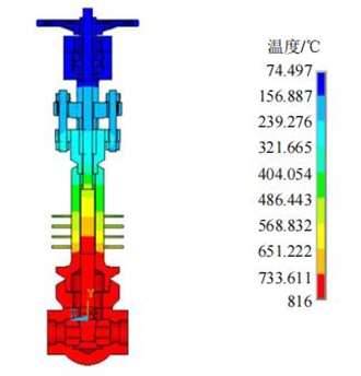
Figure 2 The cloud picture of the temperature distribution of the entire gate valve
Figures 3 to 6 are the temperature field distribution cloud diagrams of the packing set, handwheel, valve body and bonnet components. It can be seen from Figure 3 that there is a certain gradient in the temperature distribution of the packing set from bottom to top, but the temperature difference is not great. The maximum temperature value is 284°C, which is located at the bottom of the stuffing box. The minimum temperature value is 237℃, which is located at the top of the stuffing box and can meet the requirement for sealing. It can be seen from Figure 4, the lowest temperature at the outer circle of the handwheel is 74.5°C and the highest temperature is 80°C, which can meet the operating conditions. It can be seen from Figure 5, the minimum temperature of the valve body is 809°C, and the maximum temperature difference between the outer surface of the valve body and the inner cavity surface along the wall thickness direction is only 7°C, compared with the inner cavity’s temperature, that is, 816°C. The temperature distribution is more uniform. It can be seen from Figure 6 that because the radiating plate is provided for the extended cylinder of the valve bonnet, the temperature of the valve bonnet is effectively reduced from 816°C at the bottom of the extended pipe to 340°C at the top. By calculating the temperature field of the forged steel gate valve under high-temperature conditions, the maximum temperature at the bottom of the stuffing box is 284°C. The maximum temperature of the outer circle of the handwheel is 80°C, and the calculation results show that the temperatures of bottoms of the stuffing boxes and handwheels are all within the allowable range.
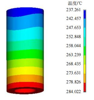
Figure 3 The cloud chart of the temperature field distribution of packing
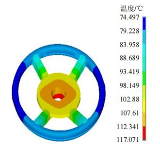
Figure 4 The cloud chart of the temperature field distribution of the handwheel
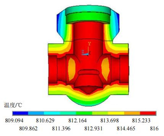
Figure 5 The cloud chart of the temperature field distribution of the valve body
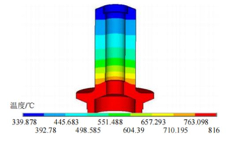
Figure 6 The cloud chart of the temperature field distribution of valve bonnets
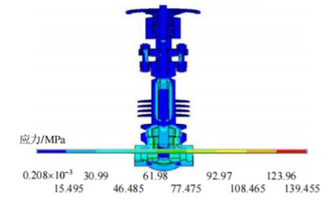
Figure 7 The cloud chart of the field distribution of the equivalent stress of the gate valve
4. The calculation of the stress field of the gate valve under normal temperature conditions
4.1 Boundary conditions and loads
In the application of boundary conditions, if full constraints are directly applied to the inlet and outlet ends of the gate valve body, thermal stresses up to several thousands MPa will be generated at the end faces of the valve body and its vicinity, which is not consistent with the actual situation. Under the actual installation and operating conditions, if a long pipe is connected to the inlet and outlet of the gate valve, the thermal expansion caused by high temperatures will be released to a certain extent without causing great stress singularity. In order to simulate the actual situation, a pipe at the inlet and outlet ends of the valve body is provided. The nominal diameter of the inlet and outlet of the valve is 80 mm. According to engineering experience, the pipe length is generally more than 5 times the pipe diameter, that is, the pipe length selected in the calculation is 400 mm, and then fixed constraints are imposed on both ends of the pipe as the displacement boundary conditions.
The calculation of the stress field of the gate valve under normal temperature conditions considers pressure of media, handwheel torque and pre-tightening forces of bolts. Design pressure of 14.6MPa is applied to the inner cavity of the valve which is in contact with the medium and the surface of other internal parts and a torque of 23.2N.m is applied to the handwheel. The stress field of the gate valve under normal temperature conditions is calculated, and then check the strength of the valve body and bonnet.
4.2 Calculation results and analysis
The equivalent stress field distribution cloud diagram of the gate valve under normal temperature conditions is shown in Figure 7. The valve body and bonnet have large stress areas, and the maximum equivalent stress is 139MPa; the stress of other parts is small. The equivalent stress distribution cloud diagrams of the valve body and bonnet are shown in Figures 8 and 9. The stress in most areas of the valve body is relatively small, which is far less than the required stress limit. At the intersection between the inlet and outlet and the valve body, the maximum stress value is 139MPa due to the sudden change in geometry, which is less than the yield strength of the material at a room temperature of 205MPa. The maximum stress of the valve bonnet is 71MPa, which is less than the material yield strength of 205MPa.
The stress evaluation of the valve body and bonnet of the gate valve under normal temperature conditions is shown in Table 3. The stress evaluation results meet the requirements for relevant standards.
Table 3 The stress evaluation of the valve body and bonnet
3.1 Boundary conditions and loads
The calculation of the temperature field of the gate valve is conducted by the function of the thermal analysis in Ansys. Ansys thermal analysis is divided into steady-state thermal analysis and transient thermal analysis. Steady-state heat transfer means that the temperature of the system does not change with time, while transient heat transfer is that the temperature of the system changes significantly with time.
In this article, the steady-state thermal analysis is used, considering that the thermal conductivity, specific heat capacity, and thermal expansion coefficient of the gate valve components change with temperatures. The steady-state temperature field of the gate valve under high-temperature conditions is calculated. The main purpose is to obtain the maximum temperature value at the bottom of the stuffing box and the outer circle of the handwheel, the temperature difference between the inner and outer walls of the pressure-bearing parts in the working process, and the distribution of the temperature field of other key components. When the finite element analysis is conducted, the first step is to establish the finite element model of the valve. The mesh model should be able to simulate the geometric shape and physical characteristics of the structure more realistically to improve the accuracy of the calculation results. In order to control the scale of calculation and increase the speed of calculation, the steady-state thermal analysis of the temperature field adopts a symmetrical model. The calculation of the temperature field needs to consider three kinds of heat transfer, namely convective heat transfer, heat conduction and radiation heat transfer. Therefore, the initial boundary conditions in Ansys steady-state thermal analysis include the application of operating temperatures, convective heat transfer coefficients and radiance. In the initial boundary condition setting of the gate valve, it is assumed that the initial temperature of its outer surface is the actual ambient temperature. The internal flow channel of the gate valve is filled with high-temperature media. A working temperature of 816℃ is applied on the valve body inner cavity which is in contact with the high-temperature medium and the surface of other inner parts. A temperature of 20°C is adopted for ambient temperatures and initial temperatures for gate valves. The thermal conductivity of steel is 48 W/(m.K). The valve is in the air, and the air convection coefficient is 12.5 W/(m2. K).
Because the radiance parameters of the material cannot be obtained, and given that when the working temperature is greater than 500°C, the heat radiation has less influence on the heat transfer result than the heat conduction and convection heat transfer. Therefore, the impact of the radiant heat dissipation of the gate valve's external wall is not considered in the calculation.
3.2 Calculation results and analysis
The steady-state thermal analysis of ANSYS obtains the result file of the overall temperature field of the gate valve over time. In addition to the temperature distribution of the gate valve, it is also used as the thermal load input condition for subsequent thermal stress calculations. Under high-temperature conditions, each part of the gate valve transfers heat through heat conduction and convection heat transfer. After the heat transfer is stable, the temperature field distribution cloud diagram of the entire gate valve is shown in Figure 2. The temperature of the gate valve decreases vertically from the valve body to the handwheel and corresponding temperature value is decreased from 816℃ to 74.5℃.
Figure 2 The cloud picture of the temperature distribution of the entire gate valve
Figures 3 to 6 are the temperature field distribution cloud diagrams of the packing set, handwheel, valve body and bonnet components. It can be seen from Figure 3 that there is a certain gradient in the temperature distribution of the packing set from bottom to top, but the temperature difference is not great. The maximum temperature value is 284°C, which is located at the bottom of the stuffing box. The minimum temperature value is 237℃, which is located at the top of the stuffing box and can meet the requirement for sealing. It can be seen from Figure 4, the lowest temperature at the outer circle of the handwheel is 74.5°C and the highest temperature is 80°C, which can meet the operating conditions. It can be seen from Figure 5, the minimum temperature of the valve body is 809°C, and the maximum temperature difference between the outer surface of the valve body and the inner cavity surface along the wall thickness direction is only 7°C, compared with the inner cavity’s temperature, that is, 816°C. The temperature distribution is more uniform. It can be seen from Figure 6 that because the radiating plate is provided for the extended cylinder of the valve bonnet, the temperature of the valve bonnet is effectively reduced from 816°C at the bottom of the extended pipe to 340°C at the top. By calculating the temperature field of the forged steel gate valve under high-temperature conditions, the maximum temperature at the bottom of the stuffing box is 284°C. The maximum temperature of the outer circle of the handwheel is 80°C, and the calculation results show that the temperatures of bottoms of the stuffing boxes and handwheels are all within the allowable range.
Figure 3 The cloud chart of the temperature field distribution of packing
Figure 4 The cloud chart of the temperature field distribution of the handwheel
Figure 5 The cloud chart of the temperature field distribution of the valve body
Figure 6 The cloud chart of the temperature field distribution of valve bonnets
Figure 7 The cloud chart of the field distribution of the equivalent stress of the gate valve
4. The calculation of the stress field of the gate valve under normal temperature conditions
4.1 Boundary conditions and loads
In the application of boundary conditions, if full constraints are directly applied to the inlet and outlet ends of the gate valve body, thermal stresses up to several thousands MPa will be generated at the end faces of the valve body and its vicinity, which is not consistent with the actual situation. Under the actual installation and operating conditions, if a long pipe is connected to the inlet and outlet of the gate valve, the thermal expansion caused by high temperatures will be released to a certain extent without causing great stress singularity. In order to simulate the actual situation, a pipe at the inlet and outlet ends of the valve body is provided. The nominal diameter of the inlet and outlet of the valve is 80 mm. According to engineering experience, the pipe length is generally more than 5 times the pipe diameter, that is, the pipe length selected in the calculation is 400 mm, and then fixed constraints are imposed on both ends of the pipe as the displacement boundary conditions.
The calculation of the stress field of the gate valve under normal temperature conditions considers pressure of media, handwheel torque and pre-tightening forces of bolts. Design pressure of 14.6MPa is applied to the inner cavity of the valve which is in contact with the medium and the surface of other internal parts and a torque of 23.2N.m is applied to the handwheel. The stress field of the gate valve under normal temperature conditions is calculated, and then check the strength of the valve body and bonnet.
4.2 Calculation results and analysis
The equivalent stress field distribution cloud diagram of the gate valve under normal temperature conditions is shown in Figure 7. The valve body and bonnet have large stress areas, and the maximum equivalent stress is 139MPa; the stress of other parts is small. The equivalent stress distribution cloud diagrams of the valve body and bonnet are shown in Figures 8 and 9. The stress in most areas of the valve body is relatively small, which is far less than the required stress limit. At the intersection between the inlet and outlet and the valve body, the maximum stress value is 139MPa due to the sudden change in geometry, which is less than the yield strength of the material at a room temperature of 205MPa. The maximum stress of the valve bonnet is 71MPa, which is less than the material yield strength of 205MPa.
The stress evaluation of the valve body and bonnet of the gate valve under normal temperature conditions is shown in Table 3. The stress evaluation results meet the requirements for relevant standards.
Table 3 The stress evaluation of the valve body and bonnet
| Evaluated parts | Stress limits | Calculation results/MPa | Allowable stress/MPa | Conclusion |
| The maximum stress of the valve body | PL plus PB being less than and equal to 1.5S | 53 | 217 | Qualified |
| The maximum stress of the valve bonnet | PL plus PB being less than and equal to 1.5S | 41 | 217 | Qualified |
The above stress calculation results under normal temperature conditions show that the component of the gate valve will not undergo plastic deformation. For high-temperature gate valves, the heat stress caused by the heat effect will cause stress concentration in the partial area of the component, causing partial failure and fatigue cracks. It is not enough to only calculate the normal temperature stress. Thermal shock or thermal cycling needs to be considered. Improving the accuracy of the calculation results of the thermal stress field of the valve is of great significance to the fatigue life estimation of the valve. Therefore, it is necessary to perform a thermo-solid coupling calculation for the high-temperature gate valve to evaluate the rationality of its design.

News
About Us
Best Categories
Useful Links