Design of Compact Integral Forged Underwater Valves
Design of Compact Integral Forged Underwater Valves
Jul 22, 2024
On this page
Abstract: This paper investigates the technical design of compact integral forged underwater valve assemblies.
Initially, using a 4-well offshore oil and gas field development project as a case study, this paper compares and analyzes the design, manufacturing, and installation processes of both the traditional clustered underwater manifold and the compact integral forged underwater valves. It also refines and summarizes the key design technologies of the compact integral forged underwater valve assembly.
Initially, using a 4-well offshore oil and gas field development project as a case study, this paper compares and analyzes the design, manufacturing, and installation processes of both the traditional clustered underwater manifold and the compact integral forged underwater valves. It also refines and summarizes the key design technologies of the compact integral forged underwater valve assembly.
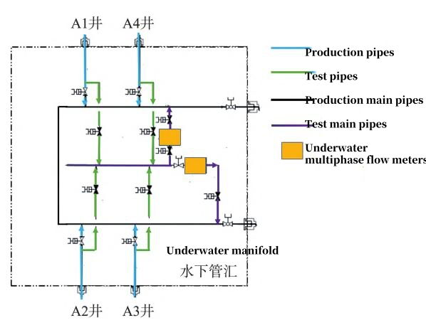
This paper uses the 4-well offshore oil and gas field development project as an example. Figure 1 illustrates the valve and pipeline layout scheme of the traditional cluster underwater dual production main manifold. It can be observed that the production logistics of each well are connected to the underwater manifold production main via a production pipeline, and another test pipeline is connected to the test main located in the middle of the underwater manifold. The pipelines connected to the underwater manifold production main and test main are equipped with hydraulically controlled, normally closed underwater gate valves for remote control of the production opening and closing of wellhead logistics. The end of the test main pipe is connected back to the two production main pipes of the manifold via two pipelines.
An underwater multiphase flowmeter is installed on each of the two pipelines to enable single-well flow measurement and create a redundant setup. A hydraulically controlled, normally closed underwater gate valve is installed on both sides of the multiphase flowmeter. While it isolates and opens the flow of wellhead logistics, it also acts as a safety valve to block the flow of logistics in the test main pipe when a leakage fault occurs in the underwater multiphase flowmeter. This ensures that the logistics flow passes through the production main pipe and is transported out normally.

Figure 1: Traditional cluster-type underwater manifold valve and pipeline layout scheme
An underwater multiphase flowmeter is installed on each of the two pipelines to enable single-well flow measurement and create a redundant setup. A hydraulically controlled, normally closed underwater gate valve is installed on both sides of the multiphase flowmeter. While it isolates and opens the flow of wellhead logistics, it also acts as a safety valve to block the flow of logistics in the test main pipe when a leakage fault occurs in the underwater multiphase flowmeter. This ensures that the logistics flow passes through the production main pipe and is transported out normally.

Figure 1: Traditional cluster-type underwater manifold valve and pipeline layout scheme
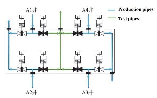
Under the condition of four production wells, the overall structural schematic diagram of the compact integral forged underwater valve group is shown in Figure 2. The key difference from the traditional slave-type underwater manifold valve and pipeline layout scheme is that the entire compact valve group can be embedded in the manifold as a module. The pipelines at both ends of the valve group enter the manifold production main as production pipelines, while the middle pipeline is used as a test pipeline, which finally merges into the manifold production main. On both sides of the entrance where the logistics of each well enters the compact valve group, a hydraulically controlled, normally closed underwater gate valve is installed. When the wellhead logistics need to flow into the manifold production main, the valves near the production pipelines at both ends of the valve group are opened. When the wellhead logistics need to flow into the test pipeline, the valves near the center of the valve group are opened to achieve the metering of the single well flow. It should be noted that the production pipelines at both ends of the compact valve group, as they respectively collect the logistics of two wells, should have a flow channel size larger than that of a single well pipeline. The test pipeline located in the center of the compact valve group provides a logistics output channel for single well flow metering, so its size can be considered the same as that of a single well pipeline.
1.3 Comparative Analysis of Traditional Manifold and Compact Integral Forged Underwater Valve Group Manifold Scheme
The traditional cluster underwater manifold and the compact integral forged underwater valve group manifold differ significantly in structural design and operating efficiency. Below is a detailed comparison and analysis of the advantages and disadvantages of these two schemes.
The traditional cluster underwater manifold connects the production pipeline and the test pipeline to the main pipeline separately and needs independent production and test pipelines for each well, resulting in a relatively dense manifold layout. Each pipeline requires separate structural support, increasing the difficulty of structural strength analysis and manufacturing. In contrast, the compact integral forged underwater valve group integrates the production and test pipelines into the flow channel inside the valve body through its integral forged design, greatly saving space. This design optimizes the manifold layout, reduces structural strength risk and the complexity of the support structure design, and makes the layout more compact and reliable.
Each valve in the traditional cluster subsea manifold is connected to the manifold through flanges or welding. As the number of valves increases, the number of connection interfaces also increases, requiring special attention to the sealing of each interface. In the compact integral forged subsea valve group, the valves are centrally installed in the middle of the valve body, involving only a few flange connections, greatly reducing the connection workload and sealing problems. This design improves reliability and simplifies the design analysis and manufacturing process, facilitating the rapid advancement of the project.
Due to the large size and weight of the traditional cluster manifold, strong construction capabilities and equipment are required for offshore installation, increasing the construction cost and operation cycle. In contrast, the compact integral forged subsea valve group significantly reduces installation difficulty due to its optimized size and weight. Selecting appropriate ship resources for installation can reduce construction requirements, save costs, and shorten the operation cycle, thereby improving the project's economic efficiency.
Under deepwater conditions, the valves in the traditional cluster manifold are relatively scattered, increasing the operational complexity and time cost of the ROV (underwater remote control robot). In the compact integral forged underwater valve group, the valve actuator is concentrated at the top of the valve body, allowing the ROV to easily operate the valve by simply positioning itself. This centralized design significantly reduces the ROV's travel, thereby reducing operation time and cost.
The design of the compact integral forged underwater valve group is particularly suitable for underwater oil and gas fields with concentrated resources. Its modular design allows for simple expansion, such as from a two-valve group to a four-valve group or a six-valve group, providing a wider range of application scenarios and higher economic benefits.
The compact integral forged underwater valve group integrates the valves, production pipelines, and test pipelines of the traditional cluster manifold into one valve body. To ensure that the valve body meets the normal production and testing function requirements underwater, the following issues must be addressed during the design stage:
The valve body of the compact integral forged underwater valve group must meet the production and testing requirements under multi-wellhead conditions. Therefore, the flow channel design is the focus of the valve body design. To ensure underwater production safety, a valve is usually installed before the wellhead flow line connects to the valve body's production pipeline and test pipeline through the jumper pipe. To ensure that the production pipeline and test pipeline inside the valve body do not interfere with each other, the outlet positions of the pipelines need to be arranged reasonably. As shown in Figure 2, the outlets of the production pipeline are located on both sides of the valve body, while the outlet of the test pipeline is located in the center. After the wellhead flow enters the valve body, it can flow to the two ends and the center according to production requirements, effectively avoiding flow channel interference inside the valve body. Additionally, the subsequent processing technology and detection problems caused by the flow channel design should be considered during the design stage. It is necessary to evaluate the technical difficulties of flow channel surfacing, processing tolerance size control, etc., under different flow channel design schemes. Additionally, factors such as on-site processing and testing equipment capabilities should be combined for comparison and selection to determine the optimal solution for the number of wellheads connected to each valve group and the flow channel design.

Figure 2: Compact integral forged underwater valve group pipeline layout scheme

Figure 2: Compact integral forged underwater valve group pipeline layout scheme
As described in Section 1.3, the ROV-operable actuator of the compact integral forged underwater valve group is situated at the top of the valve cover. The valves of the compact integral forged underwater valve group are more concentrated, and a pressure balancer is often installed on the top of the valve cover to balance the internal and external pressures of the actuator. It is necessary to analyze the actuator spacing design and pressure balancer orientation between each valve according to the actual number of valves required for the project. If necessary, consider optimizing the structural dimensions of the valve stem, valve cover, pressure balancer, etc., to ensure the ROV has sufficient operating space for the actuator of each underwater valve.
Next: Basic Information and Purchasing of Forged Steel Floating Ball Valves
Previous: Duplex Stainless Steel Forged Valves
News
About Us
Best Categories
Useful Links