Abnormal Hardness in Welding Heat Affected Zones of F91 Forged Valves (Part One)
Abnormal Hardness in Welding Heat Affected Zones of F91 Forged Valves (Part One)
Sep 23, 2022
In view of the problem of hardness reduction in the welding adjacent parts of the F91 valve used in the thermal power plant pipeline and the pipeline, the location of the failure and cause were determined, and the valve welding and on-site welding process were improved, and the valve’s hardness reached the standard requirements. It has been verified that there is no problem with hardness reduction in the welded heat-affected zone after the improvement, and the valve operates well.
1. Overview
With the development of China's energy industry, major thermal power plants have widely used forged steel blocking valves and pipes made from ASTM A182 F91 low-alloy steel. The metallographic structure of F91 low-alloy steel forms fine tempered martensite in the normalized state, and then when tempered at high temperatures, the lath is fragmented to form a sub-grain block and a meta-stable dislocation net structure, which becomes heat-strength steel with excellent heat-strength and heat-stability and can meet the requirements of high-temperature and high-pressure working conditions in thermal power plants.
When the forged valve is connected to the pipeline, the method of on-site welding is adopted. If welding and post-welding heat treatment are improper, there will be abnormal metallographic structure and low hardness, resulting in the valve not complying with DL/T 438-2016 "Technical Supervision of Metals in Thermal Power Plants" The provisions in "Hardness Values of Metal Materials Commonly Used in Power Stations" in Appendix C, that is, it does not meet the requirement of the hardness value of F91 low alloy steel reaching 175HB to 248HB.
2. The analysis of abnormal hardness
2.1 The location of the failure
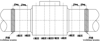
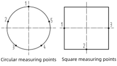
During the maintenance of the main steam pipeline of a boiler in a power plant, it was found that the hardness values at 40mm and 90mm near the welding part between the two sides of the blocking valve and the pipe were abnormal, as shown in Figure 1. The minimum hardness is 138HB, which does not meet the requirements of the DL/T 438-2016 standard for hardness values reaching 175HB to 248HB. For hardness testing in other areas, the minimum hardness value is 189HB, which meets the requirements for hardness value specified in the DL/T 438-2016 standard.


Figure 1 The schematic diagram of hardness testing areas and testing points
From the analysis of the hardness measurement values, it can be concluded that the abnormal reduction of the valve’s hardness value mainly exists in sections A, B, H, and I, within 40mm and 90mm from the center of the welding seam. Therefore, it is determined that the area with abnormal hardness exists in the welding affected zone and the welding heat affected zone, and the analysis of the welding process is carried out for the above problems.
2.2 The analysis of the welding process
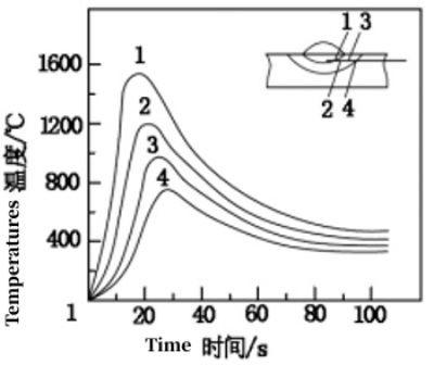
The welding arc is divided into DC welding and AC welding. When DC welding is performed, the temperature of the anode is 2326°C, the cathode 2126°C, and the arc center 5726 to 7726°C; when AC welding has a temperature of 2226°C. The welding heat diffusion is about 65% to 85%. Zone 1 is about 1512°C, zone 2 1190°C, zone 3 920°C, and zone 4 780°C, which will cause the temperature change on the workpiece, as shown in figure 2.

Figure 2 The distribution of welding temperature changes
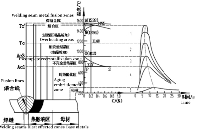
According to the welding influence temperature corresponding to the welding arc area in Figure 2 and the corresponding metallographic diagram, the following analysis is carried out, as shown in Figure 3.

Figure 3 Corresponding diagrams of welding temperature areas and metallographic phase
It can be seen from Figure 3 that the welding area has an aging embrittlement zone (base metal), an incomplete recrystallization zone (heat-affected zones), a phase-change recrystallization zone (heat-affected zones), an overheating zone (heat-affected zones), and a fusion zone (welding seams). According to the hardness measurement values, the abnormal area of hardness reduction corresponds to the incomplete recrystallization area.
The incomplete recrystallization zone is in the welding heat-affected zone, and its temperature is 727 to 912°C in the temperature zone of the high-temperature tempering zone (the high-temperature tempering temperature is 730 to 800°C). In this temperature region, the transformation temperature is higher than that, resulting in re-austenization of the metallographic structure in the region. Because the interlayer temperature needs to be guaranteed during welding, a corresponding rapid cooling method is adopted. In the cooling process, the coarse-grained austenite in the welding heat-affected zone will not be transformed into martensite in time, and will exist in the welding seam and heat-affected coarse-grained zone in the form of retained austenite, thus changing the F91 low alloy. As a result, the lath obtained by high-temperature tempering of F91 low alloy steel is changed into the metallographic state of subgrain ingots and metastable dislocation net, resulting in a decrease in the hardness of this region.
The heat treatment methods after on-site welding are mainly on-site stabilization heat treatment and high-temperature tempering heat treatment. Its main function is to eliminate welding stress and balance the metallographic morphology, so it cannot completely change the abnormal metallographic state caused by welding.
The provisions of "6.2 Preheating" in DL/T 819-2019 "Technical Regulations for Welding Heat Treatment of Thermal Power Plants" are as follows:
a. preheating before welding
When using flexible ceramic resistance heating or far-infrared radiation heating, the heating width on each side is not less than 4 times the welding thickness and not less than 100mm. When using induction heating or flame heating, the heating width on each side is not less than 3 times the thickness of the weldment, not less than 100mm.
b. heat treatment after welding
The heating width of the pipe butt joint should be selected according to the heating method and the ratio of the outer diameter (D) to the wall thickness (δ), but the minimum is not less than 100mm.
According to the above analysis, combined with the area with abnormal hardness detected at both ends (Figure 1), the detected area with abnormal hardness is within the length of 90mm, 40mm plus 50mm. Therefore, it is confirmed that the area with abnormal hardness is the welding-affected area and the post-welding heat treatment area.
1. Overview
With the development of China's energy industry, major thermal power plants have widely used forged steel blocking valves and pipes made from ASTM A182 F91 low-alloy steel. The metallographic structure of F91 low-alloy steel forms fine tempered martensite in the normalized state, and then when tempered at high temperatures, the lath is fragmented to form a sub-grain block and a meta-stable dislocation net structure, which becomes heat-strength steel with excellent heat-strength and heat-stability and can meet the requirements of high-temperature and high-pressure working conditions in thermal power plants.
When the forged valve is connected to the pipeline, the method of on-site welding is adopted. If welding and post-welding heat treatment are improper, there will be abnormal metallographic structure and low hardness, resulting in the valve not complying with DL/T 438-2016 "Technical Supervision of Metals in Thermal Power Plants" The provisions in "Hardness Values of Metal Materials Commonly Used in Power Stations" in Appendix C, that is, it does not meet the requirement of the hardness value of F91 low alloy steel reaching 175HB to 248HB.
2. The analysis of abnormal hardness
2.1 The location of the failure
During the maintenance of the main steam pipeline of a boiler in a power plant, it was found that the hardness values at 40mm and 90mm near the welding part between the two sides of the blocking valve and the pipe were abnormal, as shown in Figure 1. The minimum hardness is 138HB, which does not meet the requirements of the DL/T 438-2016 standard for hardness values reaching 175HB to 248HB. For hardness testing in other areas, the minimum hardness value is 189HB, which meets the requirements for hardness value specified in the DL/T 438-2016 standard.


Figure 1 The schematic diagram of hardness testing areas and testing points
From the analysis of the hardness measurement values, it can be concluded that the abnormal reduction of the valve’s hardness value mainly exists in sections A, B, H, and I, within 40mm and 90mm from the center of the welding seam. Therefore, it is determined that the area with abnormal hardness exists in the welding affected zone and the welding heat affected zone, and the analysis of the welding process is carried out for the above problems.
2.2 The analysis of the welding process
The welding arc is divided into DC welding and AC welding. When DC welding is performed, the temperature of the anode is 2326°C, the cathode 2126°C, and the arc center 5726 to 7726°C; when AC welding has a temperature of 2226°C. The welding heat diffusion is about 65% to 85%. Zone 1 is about 1512°C, zone 2 1190°C, zone 3 920°C, and zone 4 780°C, which will cause the temperature change on the workpiece, as shown in figure 2.

Figure 2 The distribution of welding temperature changes
According to the welding influence temperature corresponding to the welding arc area in Figure 2 and the corresponding metallographic diagram, the following analysis is carried out, as shown in Figure 3.

Figure 3 Corresponding diagrams of welding temperature areas and metallographic phase
It can be seen from Figure 3 that the welding area has an aging embrittlement zone (base metal), an incomplete recrystallization zone (heat-affected zones), a phase-change recrystallization zone (heat-affected zones), an overheating zone (heat-affected zones), and a fusion zone (welding seams). According to the hardness measurement values, the abnormal area of hardness reduction corresponds to the incomplete recrystallization area.
The incomplete recrystallization zone is in the welding heat-affected zone, and its temperature is 727 to 912°C in the temperature zone of the high-temperature tempering zone (the high-temperature tempering temperature is 730 to 800°C). In this temperature region, the transformation temperature is higher than that, resulting in re-austenization of the metallographic structure in the region. Because the interlayer temperature needs to be guaranteed during welding, a corresponding rapid cooling method is adopted. In the cooling process, the coarse-grained austenite in the welding heat-affected zone will not be transformed into martensite in time, and will exist in the welding seam and heat-affected coarse-grained zone in the form of retained austenite, thus changing the F91 low alloy. As a result, the lath obtained by high-temperature tempering of F91 low alloy steel is changed into the metallographic state of subgrain ingots and metastable dislocation net, resulting in a decrease in the hardness of this region.
The heat treatment methods after on-site welding are mainly on-site stabilization heat treatment and high-temperature tempering heat treatment. Its main function is to eliminate welding stress and balance the metallographic morphology, so it cannot completely change the abnormal metallographic state caused by welding.
The provisions of "6.2 Preheating" in DL/T 819-2019 "Technical Regulations for Welding Heat Treatment of Thermal Power Plants" are as follows:
a. preheating before welding
When using flexible ceramic resistance heating or far-infrared radiation heating, the heating width on each side is not less than 4 times the welding thickness and not less than 100mm. When using induction heating or flame heating, the heating width on each side is not less than 3 times the thickness of the weldment, not less than 100mm.
b. heat treatment after welding
The heating width of the pipe butt joint should be selected according to the heating method and the ratio of the outer diameter (D) to the wall thickness (δ), but the minimum is not less than 100mm.
According to the above analysis, combined with the area with abnormal hardness detected at both ends (Figure 1), the detected area with abnormal hardness is within the length of 90mm, 40mm plus 50mm. Therefore, it is confirmed that the area with abnormal hardness is the welding-affected area and the post-welding heat treatment area.
Next: Abnormal Hardness in Welding Heat Affected Zones of F91 Forged Valves (Part Two)
Previous: Processing forged Stainless Steel Valve Bodies with Large Diameters
News
About Us
Best Categories
Useful Links